HS-NCM Installation Document — P/N 54014:B2 04/25/2014 9
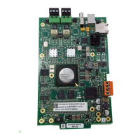
Figure 5 Installing an HS-NCM-W/MF/SF/MFSF onto the CA-1 or CA-2 Audio Chassis Assembly
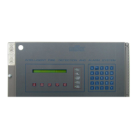
Figure 6 Door-Mounting the HS-NCM-W
6.2 Interconnecting the HS-NCM-W
When wiring consecutive HS-NCM-W boards, note that wiring may enter or exit at Port A or Port B as shown in Figure 7.
HS-NCM-W port-to-port wiring is polarity sensitive. Port A must be connected to Port B of the next HS-NCM-W. A HS-
NCM-W may be connected to any of the following devices:
• HS-NCM-W (in another panel)
• HS-NCM-WSF/HS-NCM-WMF (in another panel)
• ONYXWORKS-HNW
For information regarding these devices, refer to the documentation listed in Table 6 “Supplemental Documentation”.
NOTE: The module cannot be mounted in the ADP-4B Dress Panel when a front slot of the CHS-4 or CHS-4N
is occupied, or when either of the two front right positions of the CHS2-M2 is occupied. Always be certain there
is enough clearance to close the cabinet door when this installation is used.
A. Align HS-NCM over four PEM studs of
the CA-1 chassis as indicated.
B. Fasten with screws provided with HS-NCM.
CA1NCM_insths.wmf
CA1NCMhs.wmf
Mount a single-space
blank plate onto the ADP-
4B Dress Panel.
Single-space
blank plate
Fasten module to the plate with
four screws (included).
Note: Door mounting applications are appropriate for wire (HS-NCM-W)
only. Fiber model HS-NCM-MF/SF/WMF/WSF/MFSF must be stationary.