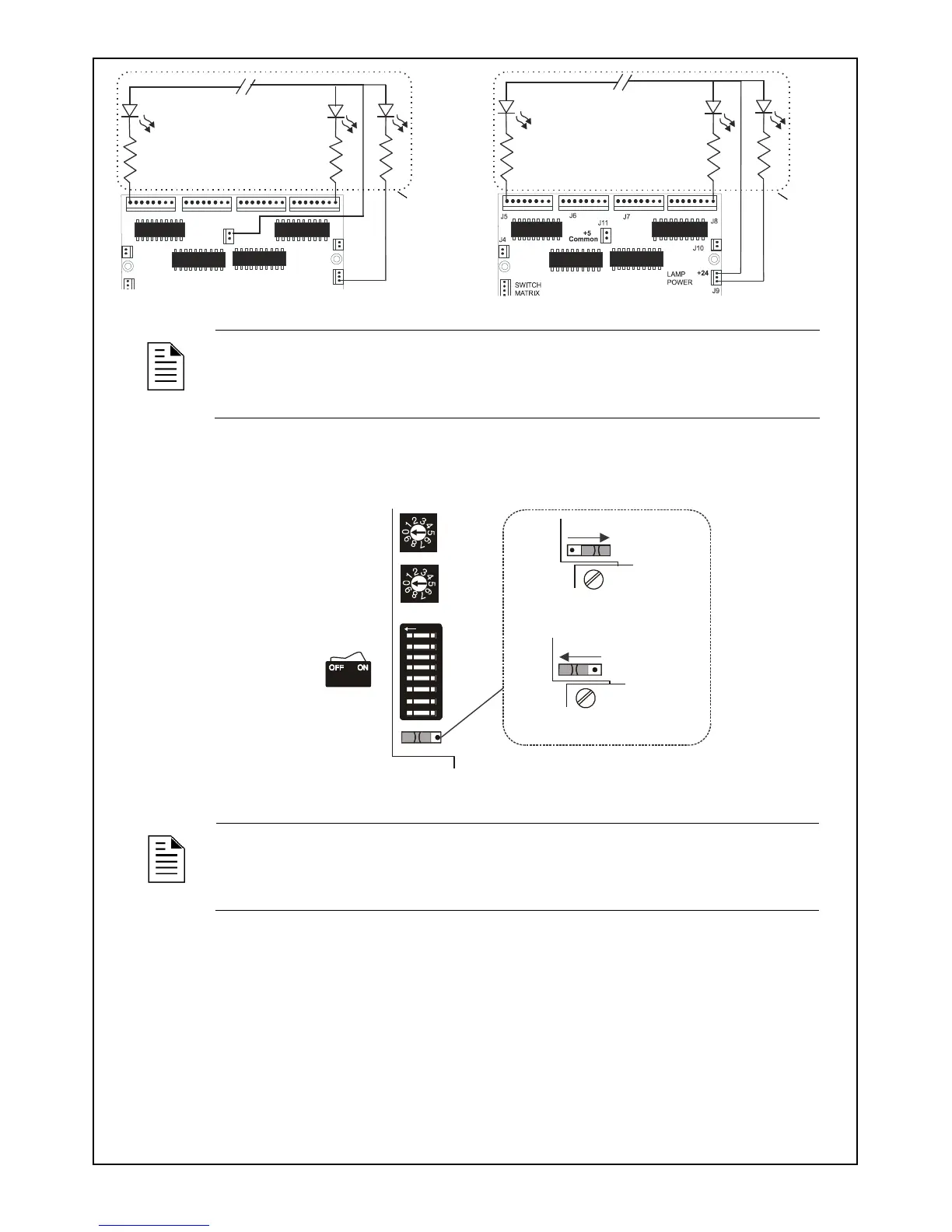
Figure 2-6 - Lamp/LED Wiring for 5 V DC
Figure 2-7 - Lamp/LED Wiring for 24 V DC
NOTE: All LEDs must be in the same room as the LDM modules.
3 Configuration
3.1 Setting the Address and Operating Modes
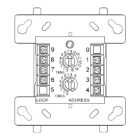
Figure 3-1 - Rotary address & DIP switches on the LDM-32
NOTE: The available address range for the LDM-32 is 2-32 (inclusive.)
1. Set a unique address for the LDM-32 using the rotary address switches along the side of the
module.
2. Set the operating mode using the DIP switches on the LDM-32. See Table 1 for a description of the
switch functions.
3. Configure annunciator points via the panel’s keypad or through VeriFire Tools. Refer to the panel’s
Programming Manual for further information on programming the annunciator.
J11
+5
Common
J6
J5
J4
SWITCH
LAMP
POWER
J7
J8
J10
J9
Custom
Graphic
Display
System
Trouble LED
(Yellow)
Point Status LEDs:
Use RED for Alarm points
YELLOW for Trouble points, and
GREEN for Output points.
Use 680 , 1.4 W resistors
for each point if using 2 mA LEDs.
Custom
Graphic
Display
System
Trouble LED
(Yellow)
Point Status LEDs:
Use RED for Alarm points
YELLOW for Trouble points, and
GREEN for Output points.
Use 10K , 1.4 W resistors
for each point if using 2 mA LEDs.
LDM-32
Lamp Driver Address
Set in the range 02-32
Ones
Tens
DIP Switch SW3
ALARM/TROUBLE mode
ALARM ONLY mode
1
2
3
4
5
6
7
8
O
F
F
SW4
SW4
Switch set to
positionOFF