SFP-400B 15124:G1 06/24/97
16
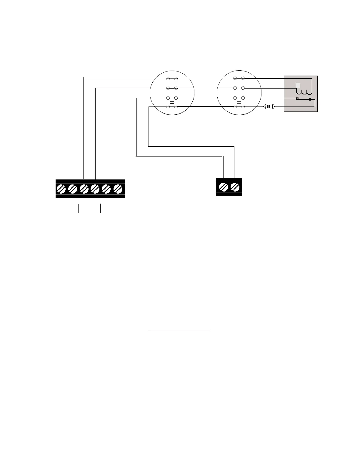
Notes on Style B and Style D field wiring:
1) The Power Supervision Relay coil leads must be connected to the last detector base 24V screw terminals.
2) Calculation of the maximum allowable resistance in the 24VDC detector power wiring:
Where:
R
MAX
is the maximum resistance of the 24V wires.
V
OM
is the minimum operating voltage of the detector or end-of-line relay, whichever is greater,
in volts.
N is the total number of detectors on the 24V supply loop.
I
S
is the detector current in standby.
N
A
is the number of detectors on the 24V power loop which must function at the same time in
alarm.
I
A
is the detector current in alarm.
I
R
is the end-of-line relay current.
24 VDC (+)
Common (-)
IDC(+)
IDC(-)
Red
Black
24 VDC (+)
Common (-)
IDC(+)
IDC(-)
UL-listed 24 VDC
Four-Wire Smoke Detectors
UL Listed
4.7K, 1/2-Watt
ELR
TB2
34
+ -
TB4
78
B+ B-
+24VR
A maximum of 200mA is available from the
+24VDC 4-wire smoke detector power circuit
on terminals 3 and 4. Any power that is drawn
from the +24VDC Non-Resettable Power on
terminals 5 and 6 must be subtracted from
available 4-wire detector power. (see Sec-
tions
"Specifications"
and
"Power"
)
IN #1
Style B Initiating Device Circuit
Initiating Device Circuits 1, 2, 3, or 4
can be used.
Listed
Power
Supervision
Relay
3.3 4-Wire Smoke Detector Connections
R
MAX
= (20.6 - V
OM
)
(N x I
S
) + (N
A
x I
A
) + (I
R
)
Refer to the Device Compatibility Document, for suitable 4-wire smoke detectors.
Figure 3.3-1: Diagram of Connections for a 4-Wire Smoke Detector
 Loading...