SFP-400B 15124:G1 06/24/97
18
1 2 3 4 5 6
+24VU +24VR +24VNR
+ - + - + -
This output is not suitable for power-
ing devices requiring filtered, regu-
lated DC power.
The combined current draws from the Resettable and Non-Resettable outputs
cannot exceed 200 mA.
TB2
Trouble Relay
One Form-C dry trouble contact is provided in the basic panel for controlling supplementary devices. It
is rated 2 amps at 30 VDC, 0.5 amps at 30 VAC (resistive) and will silence when trouble condition is cleared.
See below for terminal location.
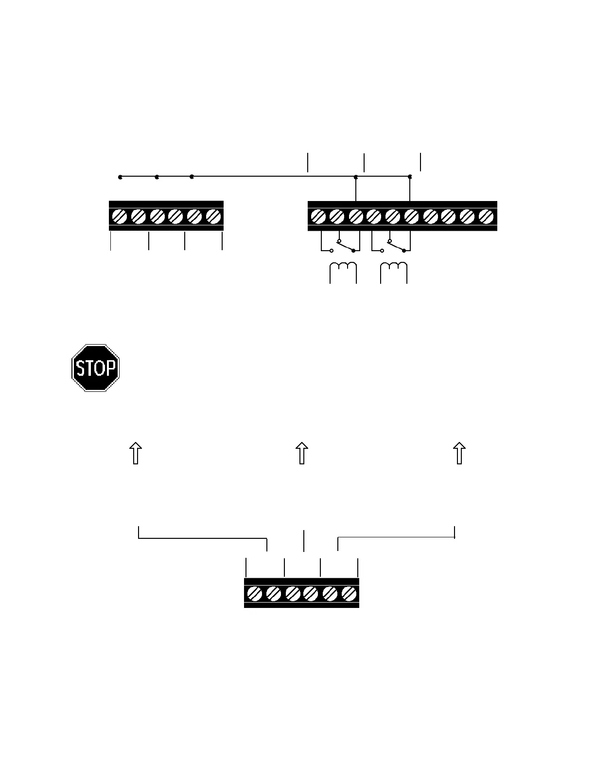
Note: The alarm and trouble Form-C dry contact relays must be power limited relays. Any Form-C dry contact
relay that may be used must be wired from one of the 24V power limited terminals as shown in the figure below
or a comparable UL listed power limited power supply.
Figure 3.5-1: Diagram of Power Terminals
AC Power
Primary power required for the SFP-400B panel is 120 VAC, 50/60 Hz, 1.2 amps and primary power
required for the SFP-400BE panel is 220/240 VAC, 50 Hz, 0.6 amps. Overcurrent protection for this circuit
must comply with Article 760 of the National Electrical Code (NEC) and/or local codes. Use #14 AWG or
larger wire with 600 volt rating.
Unregulated Power
24 VDC power for inductive-type
devices such as door holders
can be connected to TB2 termi-
nals 1(+) and 2 (-).
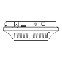
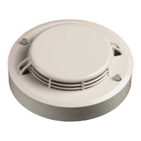
4-Wire Smoke Detector Power
24 VDC filtered, regulated, reset-
table power for 4-wire smoke de-
tectors can be obtained from TB2
Terminals 3 (+) and 4 (-).
Non-resettable Power
24 VDC filtered, regulated, non-
resettable power can be drawn
from TB2 Terminals 5 (+) and 6 (-).
3.5 Power
CAUTION: Several different sources of power can be connected to this panel. Disconnect
all sources of power before servicing. The panel and associated equipment may be
damaged by removing and/or inserting cards, modules, or interconnecting cables while
this unit is energized.
1 2 3 4 5 6
Alarm Trouble
1 2 3 4 5 6
TB2
+ - + - + -
+24VU +24VR +24VNR
TB4
ALARM TROUBLE
NO NC C NO NC C
- - -
- - -
- - -
or or
Figure 3.4-2: Alarm / Trouble Coils and Contacts