NOVAR 315 Commissioning Instructions NOVAR315
Page 2 of 10
1 INTRODUCTION
There is a warning symbol on the equipment, an exclamation mark within a triangle. This alerts the
user to refer carefully to these Commissioning Instructions before installing, commissioning or
operating the equipment.
WARNINGS
1. Installation, commissioning and maintenance should only be carried out by suitably qualified
personnel.
2. Terminations exposed during installation, commissioning and maintenance may present a hazard
unless the equipment is electrically isolated.
3. The equipment should only be operated as intended, e.g. within the specified electrical and
environmental limits.
4. Susceptibility to Electrostatic Discharge : 8 kV air discharge / 4 kV contact.
This specification applies for direct contact with the terminals and via air discharge. If the device is
opened, appropriate ESD precautions must be taken. The human body can generate potentially
damaging electrical discharges so care must be taken to earth oneself effectively before removing
the NOVAR 315 from its housing. Use of a wrist strap connected to earth through a 1 MΩ resistor
is recommended.
5. If High Voltage capacitors are to be used, set the safety lockout time before applying current to the
NOVAR 315 (refer to Section 5 for the setting procedure).
2 COMMISSIONING
The NOVAR 315 should be connected to the system according to the wiring diagram on the rear of
the case. Ensure that the current and voltage connections are made to the correct terminals and have
the required phase relationship. Capacitors must be connected on the load side of the CT.
Fuses (0.5 A rated) should be connected in the voltage inputs as shown on the wiring diagram.
The following settings need to be made :
Sequence, Safety lockout time, Stage limit, c/k, Target cosϕ, Harmonic alarm (optional), Type of
switching (rotational or linear), Type of stepping (double or single) and System Phase.
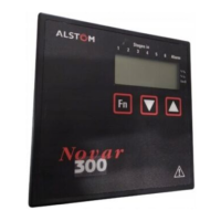
All the necessary adjustments are accessible via the controller fascia (see Figure 1).
2.1 NOVAR POWER UP
Apply voltage and current to the NOVAR 315
The NOVAR 315 should display “315” for a few seconds during its self test.
It will then enter AUTO mode and display the power factor value.
If not, see sections 2.2 and 2.3
2.2 CONNECTION ERROR
If the voltage or current connections have been made to the wrong phase, the NOVAR 315 will
display the phase angle by which the current leads the voltage to assist with connection fault-finding.
For example : At unity power factor with a reversed CT, the display will indicate 270°.
 Loading...