CAUTION OR WARNING:
Electrical shock hazard.
All safety related instructions that appear in the manual must be
observed to ensure personal safety and to prevent damage to either
the instrument or the system. If the instrument is used in a manner not
specified by the manufacturer, the protection provided by the
equipment may be impaired.
PRESENTATION
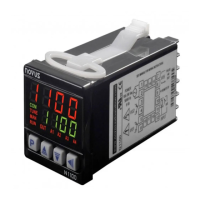
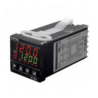
The N1100 is an extraordinarily versatile process controller. It holds
in one single instrument all the main features needed for the vast
majority of industrial processes. It accepts in a single model virtually
all the sensors and signals used in the industry and provides the
main output types required for the operation of diverse processes.
The configuration can be performed directly on the controller or through
the USB interface. The NConfig software (free) is the configuration
management tool. Connected to the USB of a Windows computer, the
controller is recognized as a serial communications port (COM) running
with a Modbus RTU protocol.
Through the USB interface, even if disconnected from the power
supply, the configuration performed in a piece of equipment can be can
be saved in a file and repeated in other pieces of equipment that
require the same configuration.
It is important that the users read carefully this manual before using
the controller. Verify if the release of this manual matches the
instrument version (the firmware version is shown when the controller
is energized).
MAIN CHARACTERISTICS
• Multi-sensor universal input (sensors and standard signals);
• Protection for open sensor in any condition;
• Relay, 4-20 mA and logic pulse control outputs all available in the
standard model;
• Self-tuning of PID parameters;
• Automatic / Manual function with “bumpless” transfer;
• Four modes of independents alarms, with functions of minimum,
maximum, differential (deviation), open sensor and event;
• Timer functions that can be associated to the alarms;
• Retransmission of PV or SP in 0-20 mA or 4-20 mA;
• Input for remote setpoint;
• Digital input with 5 functions;
• Programmable soft-start;
• 7 setpoint profile programs with 7 segments each, with the ability
to be linked together for a total of 49 segments;
• Password for parameters protection;
• Universal power supply.
CONFIGURATION / FEATURES
Select the input type (in parameter “
Table 1 – Input types
Note: All input types are factory calibrated.
OUTPUTS, ALARMS AND DIGITAL INPUTS CONFIGURATION
The controller input and output channels (I / O) can assume multiple
functions: control output, digital input, digital output, alarm output,
retransmission of PV and SP. These channels are identified as I / O
1, I / O 2, I / O 3, I / O 4 and I / O 5.
The basic controller model comes loaded with the following features:
I / O 1- output to Relay SPST-NA;
I / O 2- output to Relay SPST-NA;
I / O 5- current output, digital output, digital input;
Optionally, other features can be added, as shown under the item
“Identification” in this manual:
- 3R: I / O3 with output to SPDT relay;
- DIO: I / O3 and I / O4 as digital input and output channels;
- 485: Serial Communication