EasyManua.ls Logo

Novus N480D User Manual

Novus N480D
6 pages
To Next Page IconTo Next Page
Page #1 background imageLoading...
Page #1 background image
NOVUS AUTOMATION 1/6
Controller
N480D
UNIVERS
AL CONTROLLERINSTRUCTIONS MANUAL – V5.0x F
SAFETY SUMMARY
The symbols below are used on the equipment and throughout this
document to draw the user’s attention to important operational and
safety information.
CAUTION:
Read complete instructions prior
to installation and operation of
the unit.
CAUTION or WARNING:
Electrical shock hazard
All safety related instructions that appear in the manual must be observed
to ensure personal safety and to prevent damage to either the instrument
or the system. If the instrument is used in a manner not specified by the
manufacturer, the protection provided by the equipment may be impaired.
INSTALLATION
The controller must be installed on a panel with a square opening with
the specified dimensions. In order to fasten to the panel, remove the
clamps from the controller, introduce the controller in the panel’s
opening through the front and put the clamps back on the body of the
controller through the rear side of the panel. Firmly press the clamps in
order to fasten the controller to the panel.
The entire internal part of the controller can be removed from its
housing from the front of the panel, without needing to remove the
housing or clamps, or undo the connections. To extract the controller
from its housing, hold it from the front and pull.
Fig. 1 shows the electrical terminals of the controller.
Fig. 1 - Electrical connections of the controller
Thermocouples must be connected between pins 10 and 11. The
extension cable positive must be connected to terminal number 11.
Pt100 type sensors must be connected in 3 wires to terminals 10, 11
and 12. For Pt100 in 2 wires, terminals 11 and 12 must be
interconnected. For adequate compensation of the cable length, the
conductors of this cable must have the same section (gauge).
RESOURCES
INPUT
Table 1 shows the types of temperature sensors accepted by the
controller and the respective code used to configure the controller.
TYPE CODE RANGE
J
Tc J
Range: -110 to 950 °C (-166 to 1742 °F)
K
Tc k
Range: -150 to 1370 °C (-238 to 2498 °F)
T
Tc T
Range: -160 to 400 °C (-256 to 752 °F)
N
Tc N
Range: -270 to 1300 °C (-454 to 2372 °F)
R
Tc R
Range: -50 to 1760 °C (-58 to 3200 °F)
S
Tc S
Range: -50 to 1760 °C (-58 to 3200 °F)
B
Tc B
Range: 400 to 1800 °C (752 to 3272 °F)
E
Tc e
Range: -90 to 730 °C (-130 to 1346 °F)
Pt100
Pt
Range: -199.9 to 850 °C (-328 to 1562 °F)
Table 1 - Types of sensors accepted by the controller
CONTROL OUTPUTS AND ALARM (OUTA, OUTB, OUTC AND
OUTD)
The controller can have 2, 3 or 4 outputs, which can be configured as
control outputs or alarm outputs. These outputs are identified on the
rear panel of the controller as OUTA, OUTB, OUTC and OUTD.
The output type (control or alarm) is defined in the controller’s
configuration. The output configuration is individual and defined in the
ovt.A
,
ovt.B
,
ovt.(
, and
ovt.d
parameters respectively.
Output control is the output intended to control the process
temperature. It is possible to configure different outputs as the control
output, however, when the OUTD output is configured as the Analog
Output Control, the other control outputs are disabled.
The output control is always off when the “
Erro
message is shown
on the controller’s display, signaling a process failure, defect in the
sensor or connection error.
Alarm outputs are used for signaling and/or safety of the process. For
outputs defined as alarm output, it is also necessary to define the alarm
function (see the Alarm Function Description item of this manual).
USB INTERFACE
The USB interface is used for CONFIGURING or MONITORING the
controller. The NConfig software must be used for the configuration. It
makes it possible to create, view, save and open configurations from
the equipment or files in your computer. The tool for saving and
opening configurations in files makes it possible to transfer
configurations between pieces of equipment and to make backup
copies. For specific models, the NConfig software also makes it
possible to update the firmware (internal software) of the controller
through the USB.
For MONITORING purposes you can use any supervisory software
(SCADA) or laboratory software that supports the MODBUS RTU
communication on a serial communications port. When connected to
the USB of a computer, the controller is recognized as a conventional
serial port (COM x). Use the NConfig software or consult the DEVICE
MANAGER in the Windows CONTROL PANEL to identify the COM port
that was assigned to the controller. Consult the mapping of the
Question and Answer IconNeed help?

Do you have a question about the Novus N480D and is the answer not in the manual?

Novus N480D Specifications

Power IconPower
power supply100 to 240 Vac/dc, 50/60 Hz
optional power supply12 to 24 Vdc / 24 Vac
maximum consumption6 VA
Operating Environment IconOperating Environment
operation temperature5 to 50 °C
relative humidity80 % max. up 30 °C
altitude< 2000 m
Inputs IconInputs
internal resolution32767 levels
resolution of display12000 levels
rate of input readingup to 55 per second
Outputs IconOutputs
OUTa / OUTCRelay SPST-NA: 1.5 A / 240 Vac
OUTBVoltage pulse for SSR, 12 V max. / 20 mA
OUTD (RPR / RRR)Relay SPDT: 3 A / 250 Vac
Weight and Dimensions IconWeight and Dimensions
dimensions48 x 48 x 110 mm
approximate weight150 g
cutout in the panel45.5 x 45.5 mm

Summary

Safety Information

Important Safety Instructions

Read complete instructions prior to installation and operation of the unit.

Electrical Shock Hazard Warning

Warning about potential electrical hazards during operation.

Input Sensor Information

Accepted Sensor Types

Details on accepted temperature sensor types and configuration codes.

Controller Installation and Wiring

Electrical Terminals Diagram

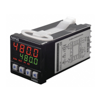
Illustration of the controller's electrical connection points.

Output and Alarm Configuration

Output Behavior During Errors

Behavior of control output when 'Erro' message is displayed.

USB Interface for Configuration

Configuration and Monitoring Uses

Primary uses of the USB interface for setup and monitoring.

Parameter Protection and Access

Levels of Configuration Protection

Table detailing configuration protection levels.

Access Password Management

Procedure for accessing protected configuration parameters via password.

Master Password for Reset

Method to reset or define new password using serial number.

General Operation and Safety Notes

USB Interface Safety Precautions

Safety caution regarding USB interface usage.

Parameter Navigation and Cycles

Parameter Organization Overview

Overview of parameter organization into cycles.

Operation Cycle Navigation

Initial display and navigation within the Operation Cycle.

Detailed Parameter Settings by Cycle

Operation Cycle Parameters

PV/SP indication, temperature rate, cycle time, program execution, run control.

Tuning Cycle Parameters

Auto-tune, PID parameters, hysteresis, and alarm setpoints.

Program Cycle Parameters

Tolerance, SP segments, time intervals, event alarms, and repetition.

Input Cycle Parameters

Input type, decimal point, unit, control action, output functions, SP limits.

Ramp and Soak Program Functionality

Level Ramp Function Configuration

How the ramp speed is set using the CALC parameter.

Ramp Function After Power Loss

Behavior of the Ramp to Level function after power loss.

Complete Ramp and Level Program

Program Structure and Persistence

Diagram of program segments and persistence of created programs.

Program Execution Steps

Steps required to initiate program execution.

Controller Calibration Procedures

Calibration Settings and Passwords

Input/output calibration, cold junction, and password settings.

Protection Cycle Configuration

Configuration of protection levels for various cycles.

Program Execution Types

Available Program Options

Overview of available program execution types.

Key Programming Functions

Program Tolerance and Repetitions

Explanation of Ptol and PEP parameters for program execution.

Auto Tuning PID Parameters

Process and recommendations for automatic PID tuning.

Alarm Functions Overview

Description of min/max, differential, sensor error, and event alarms.

Troubleshooting Controller Issues

Common Issues and Sensor Troubleshooting

Common operational issues and sensor-related troubleshooting.

Finding Controller Version and Serial Number

Accessing Version and Serial Number

Methods for viewing controller version and serial number.

Controller Technical Specifications

Physical and Electrical Specs

Dimensions, power, consumption, environmental conditions, input/output specs.

Compliance and Interface Standards

EMC, safety, USB, and panel standards.

Controller Model Identification

Model Number Components

Explanation of model number structure and variant codes.

Warranty Details

Warranty Link

Link to warranty information on the manufacturer's website.

Related product manuals