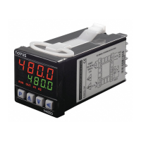
N480D Controller
NOVUS AUTOMATION 3/6
OPERATION CYCLE
TEMPERATURE
INDICATION
Control Set
Point
Temperature indication (PV) and control set point.
When turned on, the controller indicates the process
temperature on the upper display. The lower display
shows the SP value, which is the desired temperature
for the process.
Rate
Temperature increase rate. It allows the user to define
the increase or decrease characteristic of the process
temperature, the current value to the value
programmed in SP. The rate is defined in Degrees per
minute.
It is adjustable from 0.0 to 100.0 °C per
minute.
It is available when the Rate option is selected in the
parameter of the Input cycle.
Cycle Time: Time interval in minutes, that the process
must remain in the temperature defined in SP.
Adjustable from 0 to 9999.
It is available when the Rate option is selected in the
parameter of the Input cycle.
Enable
Program
Program Execution. It determines the cycle and ramp
program execution.
Executes program;
Does not execute program.
With enabled outputs (
=
program immediately enters in execution.
It is available when the Pr option is selected in the
parameter of the Input cycle.
Run
Screen that enables or disables action of the
controller over the process. It acts as a switch, turning
the controller on or off.
Outputs enables;
Outputs not enabled.
TUNING CYCLE
Auto tune
AUTO-TUNE. It enables automatic tuning of the PID
parameters (
,
,
). See chapter Auto tuning of
PID Parameters herein for more details.
Automatic tuning off;
Execute automatic tuning.
Proportional
band
PROPORTIONAL BAND. Value of the term P of the
control mode PID. In percentage of the maximum
span of the input type.
When set to zero (0), control action is ON/OFF.
Adjust of between 0 and 500.0 %.
Integral rate
INTEGRAL RATE. Value of the term I of the control
mode PID, in repetitions per minute. This constant is
not used when controller is set to ON/OFF action
(
=
).
Adjustable between 0.00 and 55.20.
derivative time
. Value of the term
of the control
mode PID, in seconds. This constant is not used when
controller is set to ON/OFF action (
=
).
Ajustable between 0 and 250.
Cycle time
CYCLE TIME. Pulse Width Modulation (PWM) period
in seconds. This constant is not used when controller
is set to ON/OFF action (
=
).
Adjustable between 0.5 and 99.99
HYSterisis
CONTROL HYSTERESIS. Hysteresis for ON/OFF
control (set in temperature units).
This parameter is only used when the controller is in
ON/OFF mode (
=
).
Alarm SP
SETPOINT FOR ALARM 1 AND 2. Tripping point for
alarm 1 and 2.
PROGRAM CYCLE
Program
Tolerance
Maximum admitted deviation of PV with respect to SP. If
exceeded, the program execution is suspended (the
internal timer freezes) until the deviation be returns back
within the defined tolerance.
The value 0 (zero) disables the function.
Program SP
Program SP’s, 0 to 9. Group of 10 values of SP that
define the Ramp and Soak profile segments.
Program Time
Time intervals of the program segments. It defines the
duration in minutes, of each of the 9 program
segments. Configurable between 0 and 9999 minutes.
Program
event
Program segment alarm (Event Alarm). Parameters
that define the alarm must be activated during the
execution of a certain program segment:
Do not activate alarm in this segment.
Activate alarm 1 when program reaches this
segment.
Activate alarm 2 when program reaches this
segment.
Activate alarms 1 and 2 when program
reaches this segment.
The alarms chosen must have its function configured
as “
”.
Repeat
Program
It determines the number of times the program must be
REPEATED, besides the initial execution. Configurable
between 0 and 9999 times. After the last execution, all
controller outputs are turned off (RUN = OFF).
INPUT CYCLE
tYPE
INPUT TYPE. Selects the input signal type to be
connected to the process variable input. Refer to
Table 1 for the available options.
This must be the first parameter to be configured.
Decimal Point
DECIMAL POINT. Defines the decimal point position.
unit
UNIT. Defines the indication unit in Celsius or
Fahrenheit.
Celsius degrees (°C);
Fahrenheit degrees (°F);
ACtion
:
Reverse action. Generally used for
heating.
Direct action. Generally used for
cooling.
OUTA, OUTB, OUTC and OUTD function:
Off
Output not used;
Output defined as control output;
Output defined as alarm output 1;
Output defined as alarm output 2;
Output defined as control output 0-20
mA (only for OUTD);
Output defined as control output 4-20
mA (only for OUTD).
SP Low Limit
Selects
adjustment for parameters relative to the SP (
,
,
).
SP High Limit
SETPOINT HIGH LIMIT. Selects maximum
adjustment for parameters relative to the SP (
,
,
).
 Loading...