EasyManua.ls Logo

Novus N120 User Manual

Novus N120
14 pages
To Next Page IconTo Next Page
Page #1 background imageLoading...
Page #1 background image
Controller N120
INSTRUCTIONS MANUAL V2.0x B
INTRODUCTION
N120 has all the main features needed for control and alarm functions in
different industrial processes. It accepts in a single model the majority
of the sensors and signals used in the industry and provides the main
output types required for dual action control (Heat and Cool) and
alarm monitoring.
The configuration can be performed directly on the controller or
through the USB interface. The NConfig software (free) is the
configuration management tool. Connected to the USB of a Windows
computer, the controller is recognized as a serial communications
port (COM) running with a Modbus RTU protocol.
Through the USB interface, even if disconnected from the power
supply, the configuration performed in a piece of equipment can be
can be saved in a file and repeated in other pieces of equipment that
require the same configuration.
The N120 in addition to being a controller is an electronic datalogger.
The logger function operates independently of the controller. The
parameter setting of the datalogger is made using LogChart-II
software.
It is important that the users read carefully this manual before using
the controller. Verify if the release of this manual matches the
instrument version (the firmware version is shown when the controller
is energized).
MAIN CHARACTERISTICS
Capable of storing 32700 registers (datalogger);
Universal multi-sensor input without hardware change;
Protection for open sensor in any condition;
Relay and logic pulse control outputs available in the standard
model;
Self-tuning of PID parameters;
Automatic / Manual function with “bumpless” transfer;
Up to 4 alarm outputs, with functions of minimum, maximum,
differential (deviation), open sensor and event;
Timer functions that can be associated to the alarms;
Digital input with 4 functions;
Programmable soft-start;
20 setpoint profile programs with 9 segments each, with the ability
to be linked together for a total of 180 segments;
Password for parameters protection;
Função LBD (loop break detector);
Universal power supply: 100-240 Vac, ±10 %.
OPERATION
The controller front panel is shown in Fig. 1.
Fig. 1 Front panel elements
Display: Shows the value and status of the controller parameters.
COM indicator: Flashes to indicate communication activity in the
RS485 interface.
TUNE indicator: Stays ON while the controller is in tuning process.
MAN indicator: Signals that the controller is in the manual control
mode.
RUN indicator: Indicates that the controller is active, with the control
output and alarms enabled.
OUT indicator: For relay or pulse control output; it reflects the actual
state of the output. If an analog output is assigned for control, the
OUT indicator lights continuously.
A1, A2, A3 and A4 indicators: signalize the occurrence of alarm
situation.
P
P Key (Program key): used to walk through the menu
parameters.
B
Back Key: used to retrocede parameters.
Increment key and
- Decrement key: allow altering the
values of the parameters.
When the controller is turned on, its firmware version is delayed for 3
seconds, after which the controller starts normal operation. The
values of PV and SP are displayed and the outputs are enabled.
In order to operate appropriately, the controller needs a configuration
that is the definition of each one of the several parameters presented by
the controller. The user must be aware of the importance of each
parameter and for each one determine a valid condition or a valid value.
Important:
Always the first parameter to set is the input type.
The parameters are grouped in levels according to their functionality
and operation easiness. The 7 levels of parameters are:
ACCESS
Free access
Reserved access
Table 1 Cycles of Parameters

Other manuals for Novus N120

Question and Answer IconNeed help?

Do you have a question about the Novus N120 and is the answer not in the manual?

Novus N120 Specifications

General IconGeneral
InputThermocouple, mA, mV, V
OutputRelay, SSR, mA
Control ActionPID, ON/OFF
Power Supply100 to 240 VAC/DC
Sampling Rate5 per second
Display4-digit LED
CommunicationRS485 Modbus RTU (optional)
Operating Temperature0 to 50°C (32 to 122°F)

Summary

Introduction

Main Characteristics

Operation

Configuration / Features

Input Type Selection

Selects the input signal type for the process variable.

Outputs

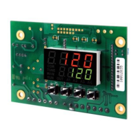
Describes available outputs and their electrical characteristics.

Digital Input

Defines the operation adopted by available digital input terminals.

Alarms Functions

Details the controller's four independent alarms and their functions.

Soft-Start

Control Mode

PID Automatic Mode

Controller defines power based on SP, PID, and other parameters.

Control 2

Describes the second independent control output for cooling processes.

LBD - Loop Break Detection Alarm

Safe Output Value with Sensor Failure

USB Interface

Installation

Description of the Parameters

Operation Level

Describes parameters accessible at the operation level.

Tuning Level

Auto-tune

Explains various automatic tuning strategies like FAST, FULL, SELF.

PID Parameters (P, I, D)

Defines Proportional Band, Integral Rate, and Derivative Time.

R&S Programs Level

Program Time Base and Number

Defines time base and selects ramp/soak profile programs.

Alarms Level

Alarm Functions (FUR1-FUR4)

Defines alarm functions like Err, Lo, Hi, dIF, etc.

I/O Cycle (Inputs and Outputs)

out1, out2, out3

Selects I/O functions for output terminals 1, 2, and 3.

d.in1

Selects the digital input function for terminal 3.

Calibration Cycle

Calibration Access (CAL16, INLC, INHC)

Details access to calibration and input/output calibration steps.

Protection of Configuration

Protection Levels (Table 7)

Defines protection levels for parameters and their access limits.

Access Password

Master Password

Programs of Ramp and Soak

Link of Programs

Event Alarm

Determination of PID Parameters

Specifications

Dimensions

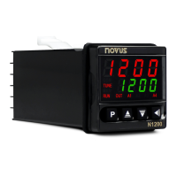
Provides physical dimensions of the controller.

Environmental Conditions

Lists operation temperature and relative humidity limits.

Input

Lists available input types for the controller.

Precision

Details the precision for different input types.

Maintenance

Problems with the Controller

Identifies common connection and programming errors.

Calibration of the Input

Details the steps for calibrating the instrument's inputs.

Calibration of the Analogical Output

Describes the process for calibrating the analog output.

Appendix 1 - Software LogChart-II

Installing LogChart-II

Instructions for installing the LogChart II software.

Running LogChart-II

Describes how to open and interface with the LogChart II software.

Configuring the Controller

Details the steps for configuring the controller using LogChart II.

Collecting Data and Viewing

Collecting the Data

Explains the process of transferring acquired data to a PC.

Viewing the Data Collected

Describes how to view collected data in graphical and tabular forms.

Determination and Selection of Serial (COM) - Windows

Determination

Explains how the operating system determines the COM port.

Selection

Important Recommendation

Anexo 2 - Serial Communication

Characteristics

Lists features and compatibility of the RS-485 interface.

Configuration of Parameters for Serial Communication

Identifies parameters for serial communication setup.

Reduced Registers Table for Serial Communication

Provides a description of common Modbus registers.

Related product manuals