EasyManua.ls Logo

Novus N1200HC User Manual

Novus N1200HC
12 pages
To Next Page IconTo Next Page
Page #1 background imageLoading...
Page #1 background image
NOVUS AUTOMATION 1/12
N12
00HC Controller
PROCESS CONTROLLER
INSTRUCTIONS MANUAL – V2.0x C
SAFETY ALERTS
The symbols below are used on the equipment and throughout this
document to draw the user’s attention to important operational and
safety information.
CAUTION:
Read the manual thoroughly
before installing and operating the
equipment.
CAUTION OR DANGER:
Electrical Shock Hazard
All safety related instructions that appear in the manual must be
observed to ensure personal safety and to prevent damage to either
the instrument or the system. If the instrument is used in a manner not
specified by the manufacturer, the protection provided by the
equipment may be impaired.
INTRODUCTION
The N1200HC is an extraordinarily versatile process controller. It
accepts in a single model virtually all the sensors and signals used in
the industry and provides the main output types required for the
operation of diverse processes.
The configuration can be performed directly on the controller or through
the USB interface. The NConfig software (free) is the configuration
management tool. Connected to the USB of a Windows computer, the
controller is recognized as a serial communications port (COM) running
with a Modbus RTU protocol.
Through the USB interface, even if disconnected from the power
supply, the configuration performed in a piece of equipment can be can
be saved in a file and repeated in other pieces of equipment that
require the same configuration.
It is important that the users read carefully this manual before using the
controller. Verify if the release of this manual matches the instrument
version (the firmware version is shown when the controller is
energized). The N1200HC main characteristics are:
Multi-sensor universal input, with no hardware change;
Protection for open sensor in any condition;
Two separate control outputs: heating and cooling;
Self-tuning of PID parameters;
Automatic / Manual function with “bumpless transfer;
Three alarm outputs in the basic version, with functions of
minimum, maximum, differential (deviation), open sensor and
event;
Timer functions that can be associated to the alarms;
Retransmission of PV or SP in 0-20 mA or 4-20 mA;
Input for remote setpoint;
Digital input with 5 functions;
Programmable soft-start;
20 setpoint profile programs with 9 segments each, with the ability
to be linked together for a total of 180 segments;
Password for parameters protection;
Universal power supply.
CONFIGURATION / FEATURES
INPUT TYPE SELECTION
The type of input to be used by the controller is defined in the device
configuration. Table 1 shows all available options.
TYPE CODE RANGE OF MEASUREMENT
J
Tc j
Range: -110 to 950 ºC (-166 to 1742 ºF)
K
Tc k
Range: -150 to 1370 ºC (-238 to 2498 ºF)
T
Tc t
Range: -160 to 400 ºC (-256 to 752 ºF)
N
Tc n
Range: -270 to 1300 ºC (-454 to 2372 ºF)
R
Tc r
Range: -50 to 1760 ºC (-58 to 3200 ºF)
S
Tc s
Range: -50 to 1760 ºC (-58 to 3200 ºF)
B
Tc b
Range: 400 to 1800 ºC (752 to 3272 ºF)
E
Tc e
Range:-90 to 730 ºC (-130 to 1346 ºF)
Pt100
Pt
Range: -200 to 850 ºC (-328 to 1562 ºF)
0-20 mA
L0.20
Linear Signals
Programmable indication from -1999 to 9999.
4-20 mA
L4.20
0–50 mV
L0.50
0-5 Vdc
L0.5
0-10 Vdc
L0.10
4-20 mA
NON
LINEAR
ln j
Non Linear Analog Signals
Indication range depends on the selected sensor.
Ln k
ln t
ln n
ln r
ln s
ln b
ln E
Ln.Pt
Table 1 - Input types
Note: All input types are factory calibrated.
CONFIGURATION OF OUTPUTS, ALARMS AND DIGITAL INPUTS
The controller input and output channels (I/O) can assume multiple
functions: control output 1 or 2, digital input, digital output, alarm
output, retransmission of PV and SP. These channels are identified
as I/O 1, I/O 2, I/O 3, I/O 4 and I/O 5.
The basic controller model comes loaded with the following features:
I/O 1- output to Relay SPST-NA;
I/O 2- output to Relay SPST-NA;
I/O 5- current output, digital output, digital input;
Optionally, other features can be added, as shown under the item
Identification in this manual:
- 3R: I/O3 with output to SPDT relay;
- DIO: I/O3 and I/O4 as digital input and output channels;
- 485: Serial Communication;
The function to be used in each channel of I/O is defined by the user
in accordance with the options shown in the Table 2.
Question and Answer IconNeed help?

Do you have a question about the Novus N1200HC and is the answer not in the manual?

Novus N1200HC Specifications

General IconGeneral
BrandNovus
ModelN1200HC
CategoryController
LanguageEnglish

Summary

Safety Alerts

General Safety Warnings

Important warnings and precautions for safe operation and installation.

Introduction

Controller Overview

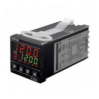
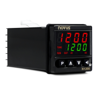
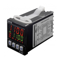
Describes the N1200HC as a versatile process controller and its features.

Configuration and Features

Input Type Selection

Defines controller input types and their measurement ranges as per Table 1.

Configuration of Outputs, Alarms, and Digital Inputs

Explains I/O channel functions and optional features available.

Configuration of Alarms

Alarm Functions

Details the nine different functions available for the controller's four alarms.

Alarm Timer Modes

Timer Function Behavior

Illustrates alarm output behavior for various timer mode configurations.

Initial Blocking of Alarm

Alarm Inhibition on Startup

Explains how initial blocking prevents alarms from triggering upon initial energization.

Control Mode

PID Automatic Mode

Discusses strategies for automatic control, including PID and ON/OFF control.

Control 2

Describes the second independent control output and its proportional action.

Run Mode

Controller Output Control

Explains how the RUN parameter enables/disables controller outputs and alarms.

Analog Retransmission of PV and SP

PV/SP Signal Output

Details retransmission of PV and SP values via analog output (0-20 or 4-20 mA).

Soft-Start

Gradual Power Delivery

Describes the soft-start feature to avoid abrupt power variations to the load.

Remote Setpoint

External Setpoint Input

Explains how setpoint values can be defined by an external analog signal.

LBD - Loop Break Detection

Loop Stability Monitoring

Details the LBD function for detecting control loop breaks and signaling occurrences.

Safe Output Value with Sensor Failure

Sensor Failure Output Handling

Describes how the control output is set to a safe condition upon sensor failure.

USB Interface

Configuration and Monitoring via USB

Explains the use of the USB interface with NConfig software for configuration.

Installation and Connections

Panel Mounting Procedure

Outlines the steps for fastening the controller onto a panel.

Recommendations for Installation

Wiring and Power Supply Guidelines

Provides recommendations for signal wiring, power supply, and noise filtering.

Electrical Connections

Back Panel Connections Overview

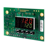
Shows the controller's internal circuits and back panel terminal layout.

Power Supply Connections

Details the wiring for power supply connections to the controller.

Input Connections

Explains wiring for thermocouple, mV, and Pt100 input signals.

Connections for Alarms and Outputs

Describes wiring for alarm outputs and control outputs like SSR pulse.

Operation

Front Panel Identification

Identifies the parts of the controller's front panel, including displays and keys.

Configuration Parameters

Operation Level Parameters

Describes the first level of parameters, accessible via the 'P' key.

Access Password

Password Entry and Protection

Explains the necessity of passwords for accessing protected parameter levels.

Protection of the Access Code

Security Against Incorrect Attempts

Details the lockout mechanism after multiple failed password attempts.

Master Password

Password Recovery Mechanism

Explains how to use the Master Password to reset a forgotten access password.

Programs of Ramp and Soak

Program Linking

Describes how to link multiple ramp and soak programs for sequential execution.

Event Alarm Configuration

Explains how to associate alarms with specific segments of a program.

Determination of PID Parameters

PID Tuning Methods

Discusses automatic and auto-adaptive tuning for PID control parameter determination.

Maintenance

Problems with the Controller

Lists common controller issues and their descriptions for troubleshooting.

Calibration of the Input

Input Signal Calibration Procedure

Outlines the steps for calibrating input signals for accurate readings.

Auto Tuning and Auto-Adaptive Tuning

Tuning Process and Options

Explains the automatic and auto-adaptive tuning process and available options (FAST, FULL, SELF).

Manual PID Parameter Adjustment

Parameter Adjustment Guidance

Provides guidance for manual adjustment of PID parameters based on observed process behavior.

Analog Output Calibration

Analog Output Calibration Procedure

Step-by-step guide for calibrating the analog output channel.

Serial Communication

Communication Characteristics

Details RS-485 compatibility, MODBUS protocol, and connection parameters.

Modbus Registers and Communication Protocol

Explains Modbus commands, reduced registers, and holding registers table.

Specifications

Dimensions and Electrical Characteristics

Lists physical dimensions, power supply, and environmental conditions.

Identification

Model and Optional Features

Identifies controller model, optional I/Os, digital communication, and power supply options.

Warranty

Warranty Information Access

Provides information on how to access warranty conditions and support.

Related product manuals