EasyManua.ls Logo

Novus N321 User Manual

Novus N321
6 pages
To Next Page IconTo Next Page
Page #1 background imageLoading...
Page #1 background image
NOVUS AUTOMATION 1/6
N321, N322, N323
TEMPERATURE CONTROLLERS
USER GUIDE
– V1.8x / V2.0x
1. SAFETY ALERTS
The symbols below are used in the device and throughout this
manual to draw the user’s attention to valuable information related to
device safety and use.
CAUTION:
Read the manual fully before
installing and operating the
device.
CAUTION OR HAZARD:
Risk of electric shock.
All safety recommendations appearing in this manual must be
followed to ensure personal safety and prevent damage to the
instrument or system. If the instrument is used in a manner other
than that specified in this manual, the device’s safety protections may
not be effective.
2. SUMMARY
1. SAFETY ALERTS ...................................................................................... 1
2. SUMMARY ................................................................................................. 1
3. INTRODUCTION ....................................................................................... 1
4. SPECIFICATIONS ..................................................................................... 1
5. ELECTRICAL CONNECTIONS ................................................................. 2
5.1 N321 MODEL ..................................................................................... 2
5.2 N322 MODEL ..................................................................................... 2
5.3 N323 MODEL ..................................................................................... 3
5.4 INSTALLATION RECOMMENDATIONS........................................... 3
6. OPERATION .............................................................................................. 3
6.1 LEVEL 1 SETPOINT ADJUSTMENT LEVEL ................................. 3
6.2 LEVEL 2 OPERATION MODE LEVEL ........................................... 3
6.3 LEVEL 3 CALIBRATION LEVEL .................................................... 4
7. OPERATION .............................................................................................. 5
7.1 N321 MODEL: OPERATION ............................................................. 5
7.2 N322 AND N323 MODELS: OPERATION ........................................ 5
7.3 N322 AND N323 MODELS: ALARM FUNCTIONS ........................... 5
7.4 N323 MODEL: ALARM TIMER .......................................................... 5
8. CONFIGURATION PROTECTION ............................................................ 5
8.1 CONFIGURATION PROTECTION OPERATION ............................. 6
9. MASTER PASSWORD .............................................................................. 6
9.1 HOW TO USE YOUR MASTER PASSWORD .................................. 6
10. ERROR INDICATION ................................................................................ 6
11. SERIAL COMMUNICATION ...................................................................... 6
11.1 FEATURES ........................................................................................ 6
11.2 PARAMETER CONFIGURATION ..................................................... 6
11.3 COMMUNICATION PROTOCOL ...................................................... 6
11.4 REGISTER TABLE ............................................................................ 6
12. WARRANTY .............................................................................................. 6
3. INTRODUCTION
N321, N322, and N323 are temperature controllers for heating and
cooling. They are distinguished by the number of outputs available:
N321: It has 1 output channel: OUT1.
N322: It has 2 output channels: OUT1 and OUT2.
N323: It has 3 output channels: OUT1, OUT2, and OUT3.
The models are subdivided by the type of temperature sensor
supported:
NTC: Model accepting only the NTC sensor.
Pt100: Model accepting only the Pt100 sensor.
J/K/T: Model accepting only J, K and T sensors.
The features of each controller are in accordance with the purchase
order and are shown on the label attached to the body of the
controller itself.
Example of the label of an N323 model:
Figure 1 Identification label
These models may have differences in power supply and the
availability of an RS485 communication channel.
4. SPECIFICATIONS
Sensor Input: The choice of sensor is made at the time of purchase
and shown on the controller identification label. There are three
options:
NTC Input:
Type: ............ NTC Thermistor, 10 kΩ @ 25 °C; β25/85 = 3435 K; 1 %
Measurement range: .............................. -50 to 120 °C (-58 to 248 °F)
Measurement accuracy: ....... 0.6 °C/F between -19.9 and 99.9 °C/F
............................................................................. 1 °C/F elsewhere
Pt100 Input:
Type: ............................................................................. Pt100,
α = 385
Measurement range: .............................. -50 to 300 °C (-58 to 572 °F)
Measurement accuracy: ........................ 0.2 % F.S. ± 2 °C @ 25 °C
J/K/T Input:
Measurement range J: ................................ 0 to 600 °C (32 to 999 °F)
Measurement range K: ............................ -50 to 999 °C (32 to 999 °F)

Other manuals for Novus N321

Question and Answer IconNeed help?

Do you have a question about the Novus N321 and is the answer not in the manual?

Novus N321 Specifications

General IconGeneral
InputThermocouple, Pt100, 4-20 mA
OutputRelay, 4-20 mA
Power Supply100-240 V AC/DC
Control ActionPID, ON/OFF
CommunicationRS485 Modbus RTU
Operating Temperature0 to 50 °C / 32 to 122 °F
ProtectionIP65 on front panel
Accuracy±0.25% of full scale
AlarmUp to 2 alarms

Summary

Safety Alerts and Precautions

General Safety Warnings

Essential safety information and hazard warnings for device installation and operation.

Introduction to Temperature Controllers

Controller Models Overview

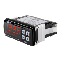
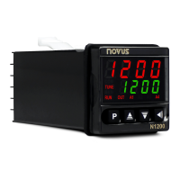
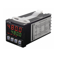
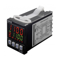
Details N321, N322, N323 models and their distinguishing output channels.

Sensor Type Variations

Explains model subdivisions based on supported sensor types: NTC, Pt100, J/K/T.

Device Identification Label

Illustrates the controller's identification label for model and specification details.

Technical Specifications

Sensor Input Specifications

Details measurement ranges and accuracy for NTC, Pt100, and J/K/T sensor inputs.

Electrical Connections

N321 Model Wiring

Diagram and description for connecting the N321 model's power, outputs, and sensor.

Pt100 Sensor Wiring

Instructions for connecting Pt100 sensors, covering both 2-wire and 3-wire configurations.

Thermocouple Sensor Wiring

Diagram for connecting thermocouple sensors (J, K, T) to the controller.

N322 Model Wiring

Diagram and description for connecting the N322 model's power, outputs, and sensor.

N323 Model Wiring

Diagram and description for connecting the N323 model's power, outputs, and sensor.

Installation Recommendations

Wiring and Power Supply Guidance

Recommendations for input signal wiring, power supply, and noise suppression.

System Failure Considerations

Essential advice on anticipating system failures and controller protection limitations.

Controller Operation

Parameter Levels Overview

Explanation of the controller's parameter organization into levels for configuration.

Level 0: Temperature Measurement

Initial display state showing measured temperature after power-on.

Level 1: Setpoint Adjustment

Procedure for adjusting the desired temperature setpoint (SP) using keys.

Level 2: Operation Mode Settings

Configuration of operational parameters like units, sensor type, and setpoint limits.

N321 Model Operation

Describes how the N321 controller uses its single output for process control.

N322 and N323 Models Operation

Explains multi-output applications for alarm control and multi-stage temperature regulation.

Alarm Functions (N322/N323)

Details the alarm functions available for outputs 2 and 3 on N322 and N323 models.

N323 Model Alarm Timer

Configuration of timed alarm functions (T1, T2) for outputs 2 and 3 on the N323 model.

Operation Mode Parameters

Unit and Sensor Type Configuration

Setting the temperature display unit and the sensor type for thermocouples.

Offset and Setpoint Limit Settings

Adjusting temperature offset for accuracy and defining lower/upper setpoint limits.

Output Action Configuration

Configuring the action type for control outputs (heating/cooling) and alarms.

Calibration Level

Calibration Access and Safety

Instructions on accessing calibration level and navigating safely.

Calibration and Protection Parameters

Details on calibration adjustments (offset, gain, cold junction) and parameter protection.

Serial Number Display

Information on how to view the controller's electronic serial number digits.

Configuration Protection

Protection Parameter Settings

Using PAS, Prt, and PRC parameters to define and manage configuration protection levels.

Master Password Management

Password Protection Operation

How to use the PAS parameter to access protected levels with the correct password.

Master Password Calculation

Method for deriving the master password using the controller's serial number.

Using the Master Password

Steps to enter the master password and set a new user password.

Error Indications

Error Messages and Output Behavior

Description of error codes displayed and their effect on control output.

Serial Communication

RS485 Interface Features

Overview of RS485 signals, connection capabilities, and transmission parameters.

Communication Parameter Configuration

Setting the Addr parameter for controller communication address on the RS485 network.

Communication Protocol and Registers

Details on MODBUS RTU protocol support and key register addresses for data access.

Warranty Information

Related product manuals