N321, N322, N323
NOVUS AUTOMATION 3/6
conductors must all have the same electrical resistance (cross-
section).
5.3 N323 MODEL
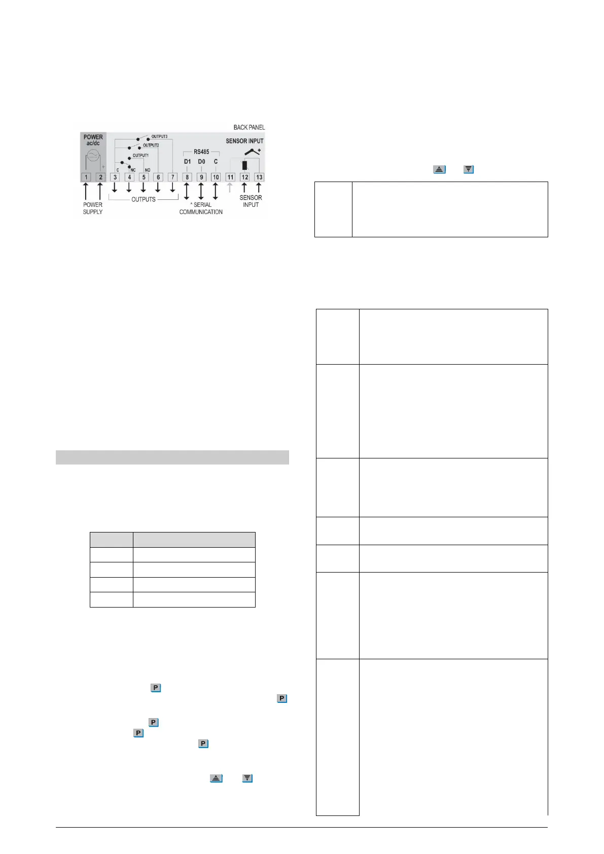
The figures below show the connection terminals for the N323
sensor, power supply, and output:
Figure 7 – Connections
* The serial communication feature is not always available in N323.
Pt100 3-wire. For 2-wire connection, terminals 11 and 13 must be
interconnected. For proper cable resistance compensation, the
conductors must all have the same electrical resistance (cross-
section).
5.4 INSTALLATION RECOMMENDATIONS
• Input signal conductors should run through the plant separate
from output and supply conductors. If possible, in grounded
conduits.
• The power supply for the electronic instruments must come from
a network dedicated to the instrumentation.
• It is recommended to use RC FILTERS (noise suppressor) in
contactor coils, solenoids, etc.
• In control applications, it is essential to consider what can
happen when any part of the system fails. The controller internal
devices do not guarantee full protection.
6. OPERATION
Before use, the controller must be configured. To configure it, you
must set values for the parameters that determine how the
equipment operates.
These configuration parameters are organized in groups or Levels,
called Parameter Levels.
LEVEL RELATED FUNCTIONS
0 Temperature measurement
1 Setpoint adjustment
2 Operation mode
Table 1 – Parameter levels
When you turn on the controller, the display shows the version of the
equipment for 1 second. This information is important for eventual
consultations with the manufacturer. Then, the controller starts
presenting the temperature value measured by the sensor. This is
level 0 or the Temperature Measurement level.
To access level 1, press
for 1 second until SP1 parameter
appears. To return to the temperature measurement level, press
again.
To access level 2, press for 2 seconds until VNT parameter
appears. Release the
key to remain at this level. To access the
other parameters of this level, press
again. After the last
parameter, the controller returns to the temperature measurement
level.
To change the parameter values, press the
and
keys until
you get the desired values.
Notes:
1. The controller saves the programming when you move from
one parameter to another. Only then will it be considered valid.
2. If the keys are not used for a time longer than 20 seconds, the
controller returns to the measuring level, finishing and saving
the configuration done so far.
6.1 LEVEL 1 – SETPOINT ADJUSTMENT LEVEL
At this level, only the Setpoint parameter (SP) is displayed. It defines
the desired temperature value for the system. The current value of
SP is shown alternately with the parameter.
To program the desired value, use
and
keys.
Setpoint
Setpoint values for the action of outputs 1, 2 and 3.
These values are limited to the values programmed in
SPL
and
in the Operation Mode cycle.
The available parameters are according to the model.
6.2 LEVEL 2 – OPERATION MODE LEVEL
Displays the sequence of the remaining parameters to be set. The
parameters are shown alternately with their values.
The number of outputs depends on the controller model.
Unit
Temperature unit. It allows you to choose the display
unit of the measured temperature.
Temperature in Celsius degrees.
Temperature in Fahrenheit degrees.
Type
Type of temperature sensor to be used.
This parameter is only available in models for
THERMOCOUPLE sensors, where you can choose
between the J, K, and T thermocouples.
Thermocouple
Offset
Correction value for temperature indication.
Allows you to make small adjustments to the
temperature indication to correct measurement errors
that appear, for example, when replacing the NTC
temperature sensor.
SP Low Limit
Must be defined with a value lower than
.
SP High Limit
Must be defined with a value higher than
.
Action 1
Output 1 action type:
Control with Reverse Action. Suitable for
heating. Turns on the control output when the
temperature is below SP.
Control with Direct Action
cooling. Turns on the control output when the
temperature is above SP.
Action 2
Action 3
Output 2 and 3 action type:
Control. Reverse action for heating.
Control. Direct action for cooling.
Minimum temperature alarm.
Maximum temperature alarm.
Minimum temperature alarm with initial
blocking.
Maximum temperature alarm with initial
blocking.