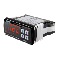
N321, N322, N323
NOVUS AUTOMATION 6/6
8.1 CONFIGURATION PROTECTION OPERATION
The PAS parameter appears at the beginning of the protected level.
If you enter the password correctly, you can change the parameters
of the protected levels. If you do not enter the password correctly or
simply pass by this parameter, the parameters of the protected levels
can only be viewed and not changed.
Important notes:
1. When you enter an incorrect password 5 consecutive times, the
equipment will prevent new attempts for 10 minutes.
If you do not remember the current password, you can enter a
master password, which only allows you to set a new
password.
2. The equipment leaves the factory with password 111.
9. MASTER PASSWORD
The master password, which allows you to set a new password for
the controller, uses the serial number of the equipment. It is
composed as follows:
[ 1 ] + [ largest number of SN2 ] + [ largest number of SN1 ] +
[ largest number of SN0 ]
The master password for an equipment with serial number 97123465
is: 1936
Example: 1 +
sn2 = 97; sn1 = 123; sn0 = 465 = 1 + 9 + 3 + 6
9.1 HOW TO USE YOUR MASTER PASSWORD
1. In the Pas parameter, enter the master password.
2. In the PA( parameter, enter any new non-zero (0) password.
3. Use the new password.
10. ERROR INDICATION
On the display, the controller shows messages that correspond to
problems related to temperature measurement. Whenever they are
displayed, the control output relay will be turned off immediately.
• The temperature has exceeded the upper limit of
the sensor range.
• Pt100 or T/C sensor broken. NTC sensor short-
circuited.
• The temperature has exceeded the lower
the sensor range.
• Pt100 or T/C sensor short-circuited. Broken NTC
sensor.
Table 3 – Error indications
11. SERIAL COMMUNICATION (1.8 VERSION)
The controller can optionally be supplied with an RS485 serial
communication interface, asynchronous, for communication with a
supervisor software.
11.1 FEATURES
• Signals compatible with RS485 standard.
• 2-wire connection between 1 master and up to 31 slave
controllers in bus topology. When using multi-output converters,
you can reach up to 247 nodes.
• Maximum connection distance: 1000 meters.
• Rate: 9600 bps
• Data bits: 8
• Parity: None
• Stop bits: 1
The RS485 signals are:
D0
D -
A
Inverted bidirectional data line.
C
Optional connection that improves
communication performance.
Table 4 – RS485
11.2 PARAMETER CONFIGURATION
To use serial communication, you must set the following parameter:
addr: Controller communication address.
11.3 COMMUNICATION PROTOCOL
The equipment supports the slave MODBUS RTU protocol, available
in most supervision software on the market.
The Modbus commands available are the following:
03 – Read Holding Register
06 – Preset Single Register
Command 03 (Read Holding Register) reads up to 4 consecutive
registers.
11.4 REGISTER TABLE
The following are the most used registers. For complete information,
refer to the Register Table for Serial Communication, available for
download in the product page.
ADDRESS PARAMETER REGISTER DESCRIPTION
0000 SP active Read: Setpoint da OUTPUT1.
Write: Setpoint da OUTPUT1.
Range: From
to the value set in
.
Read: Measured temperature variable.
Write: Not allowed.
Range: Equals the range of the sensor
used by the equipment.
Table 5 – Register table
12. WARRANTY
Warranty conditions are available on our website
www.novusautomation.com/warranty.