N480D Controller
NOVUS AUTOMATION 5/6
PROGRAM TOLERANCE FUNCTION -
The “
” program tolerance program defines the maximum error
limit between the PV and SP values during program execution. If this
limit is exceeded, the timing of the segment (Pt1…Pt9) is interrupted
until the error is within the established tolerance. With a value > 0, the
user indicates in the program that priority must be given to PV
regarding the determined time values.
If zero tolerance (
=
) is programmed, the controller executes
the program defined without considering eventual errors between PV
and SP. Thus, the user defines that the priority be given to the program
execution time.
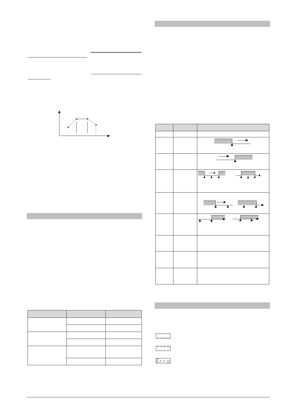
PROGRAMS WITH FEW SEGMENTS
In order to execute a program with a smaller number of segments, just
program 0 (zero) for the time interval that follows the last segment of
the desired program.
Fig. 4- Example of a program with only 3 segments
SUCCESSIVE REPETITIONS OF A PROGRAM
The elaborated program can be repeated several times, always
restarting immediately after each execution.
The
(rePeat Program) parameter, in the Program cycle,
configures the number of times the program must be REPEATED. It
determines the number of executions beyond the initial execution.
With zero (0), the program is executed only one time. It will not be
repeated.
Important: After the last execution of the program, all controller outputs
are turned off and the RUN parameter changes to OFF.
AUTO TUNING OF PID PARAMETERS
During the automatic tuning the process is controlled in ON / OFF
mode in the programmed SP - the Ramp to Level function is disabled.
The automatic tuning may take many minutes to the concluded,
particularly in slow processes. Some recommendations for the
automatic tuning process are:
• Program SP to a value close to the point at which the process will
operate after tuning.
• Enable automatic tuning on the “
” screen by selecting
.
• Program the value
on the “
” screen.
The “TUNE” indicator on the display stays lit until the completion of the
automatic tuning process.
During the execution of automatic tuning, large oscillations can be
induced in the process around the set point. Check if the process
supports these oscillations.
If the automatic tuning does not result in a satisfactory control, refer to
Table 2 for guidelines on how to correct the behavior of the process:
Proportional Band
Great oscillation Increase
Rate of Integration
Great oscillation Decrease
Derivative Time
instability
Decrease
Table 3 - Guidance for manual adjustment of the PID parameters
ALARMS FUNCTIONS
The minimum and maximum alarms are used to signalize extreme
temperature values. These extreme values are defined on the “
”
and “
” screens.
Differential alarms are used to signalize deviations between temperature
and set point control (SP). Values defined by user on the “
” and
“
” screens represent the values of these deviations.
Initial blocking prevents alarm activation when the controller is turned
on until the temperature reaches the SP value for the first time.
The error alarm in the sensor allows to signalize errors in the sensor.
The Level End function (
) determines that the alarm be activated
the end of the cycle.
With Event Alarm, an alarm is activated during execution of a certain
program segment.
Table 4 illustrates the operation of each alarm function, using alarm 1
as an example, and presents its identification code on the “
” e
“
” screens:
Output is not used as alarm.
value
value
(diFerential)
Differential
(diFerential
SPAn positive SPAn negative
Differential
(diFerential
High)
(input Error)
Activated when the input signal of PV is
interrupted, out of the range limits or
Pt100 in short-circuit.
Activate at the end of the cycle time.
Once the alarm is triggered, pressing any
(ramp and
Can be activated at a specific segment of
program.
Table 4 – Alarm functions
Where SPAn refers to Setpoints of Alarm
and
.
PROBLEMS WITH THE CONTROLLER
Connection errors and inadequate programming are the most common
errors found during the controller operation. A final revision may avoid
loss of time and damages. The controller displays some messages to
help the user identify problems.
: Sensor measuring temperature below the specified
minimum.
: Sensor measuring temperature above the specified
maximum.
: Controller failure or sensor error, examples: Thermocouple
open, Pt100 open in short circuit or poorly connected.
If the “
” message persists after analysis of the
installation, contact manufacturer informing equipment’s
Serial Number.
 Loading...