Installation & Operation Manual │ FTG
Table 9-2 Minimum and Maximum Modulation Rates
Min. Modulation
Rate (RPM)
Max. Modulation
Rate (RPM)
Min. Modulation
Rate (RPM)
Max. Modulation
Rate (RPM)
Carbon Monoxide - Never leave the unit operating while producing Carbon Monoxide
(CO) concentrations in excess of 175ppm. Failure to follow this warning may result in
serious injury or death.
Manifold Pressure – DO NOT adjust or measure the Manifold Pressure of boiler models
FTG 600-1400; the correct manifold pressure is factory set. Field adjustment could
result in improper burner operation resulting in fire, explosion, property damage or death.
Adjustments to the Throttle/Input Adjustment Screw may only be made by a qualified
gas technician, while using a calibrated combustion analyzer capable of measuring CO
2
and CO. Adjustments may only be performed if the gas line pressure is maintained above
minimum levels throughout the duration of the test, see Table 9-1. Failure to follow these
instructions may result in serious injury or death.
Flue Gas Analysis and Adjustment
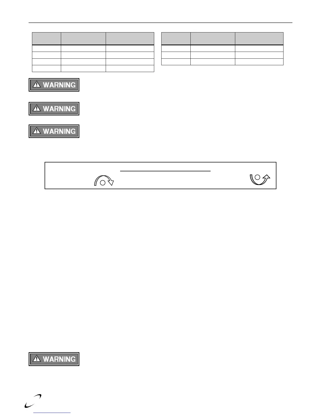
Throttle / Input Screw Adjustments – The boiler is equipped with a Throttle/Input Adjustment Screw, located
at the Gas Valve; see Figures 9-1(a) & 9-1(b); it is used to adjust the flow of gas leaving the Gas Valve
entering the Venturi and then the combustion air stream. Turn the Throttle Screw in (clockwise) to reduce
the flow of gas, make combustion leaner, and reduce the concentration of CO
2
in the flue gases. Turn the
Throttle screw out (counterclockwise) to increase the concentration of CO
2
and flow of gas in the combustion
air stream. Typical adjustment required is 0-1/8 of a turn in or out from the factory setting. See Figure 9-1
for Throttle screw location and Table 9-1 for appropriate CO
2
levels.
Combustion Calibration - To calibrate burner operation, perform the following procedure using a calibrated
combustion analyzer capable of measuring CO
2
and CO from Natural and Propane Gas burning boilers:
1. Operate the unit at the maximum modulation rate, see Table 9-2.
2. Ensure the gas line pressure is maintained within tolerance, see Table 9-1.
3. While at the maximum modulation rate, measure the CO
2
and CO; adjust as necessary, using the Throttle
Screw, to be within the limits listed in Table 9-1.
4. Operate the unit at the minimum modulation rate (see Table 9-2). Ensure the combustion remains
smooth and CO
2
and CO values are lower than the values obtained during maximum modulation, as per
notes in Table 9-1. If not, do not adjust further, contact NTI for assistance.
5. For FTG 2000-2400 models converted to LP, perform the Gas Valve Offset Check/Adjustment procedure
detailed in Figure 9-2.
Each FTG boiler is factory set to operate with Natural Gas, for boilers field converted to operate with Propane
Gas, a flue gas analysis and adjustment is mandatory. See Natural to LP Conversion Instructions included with
the boiler.
Failure to perform the flue gas analysis and adjustment detailed in this section may result
in erratic and unreliable burner operation, leading to reduced efficiency, increased fuel
consumption, reduced component life, heat exchanger combustion deposits, and general unsafe operation.
Failure to follow these instructions may result in serious injury or death.
Analysis – Perform flue gas analysis, and adjust throttle/input screw as required until CO
2
and CO levels are
within acceptable limits.
Throttle/Input Adjustment Screw
Increase gas
Turn Counter Clockwise
Decrease gas
Turn Clockwise