Offset Adjustment Procedure:
1) Differential Pressure Manometer –
obtain a meter capable of measuring
differential pressure (“+” and “-“ ports)
with a minimum graduation of 0.01
inches w.c. (or 1 Pa).
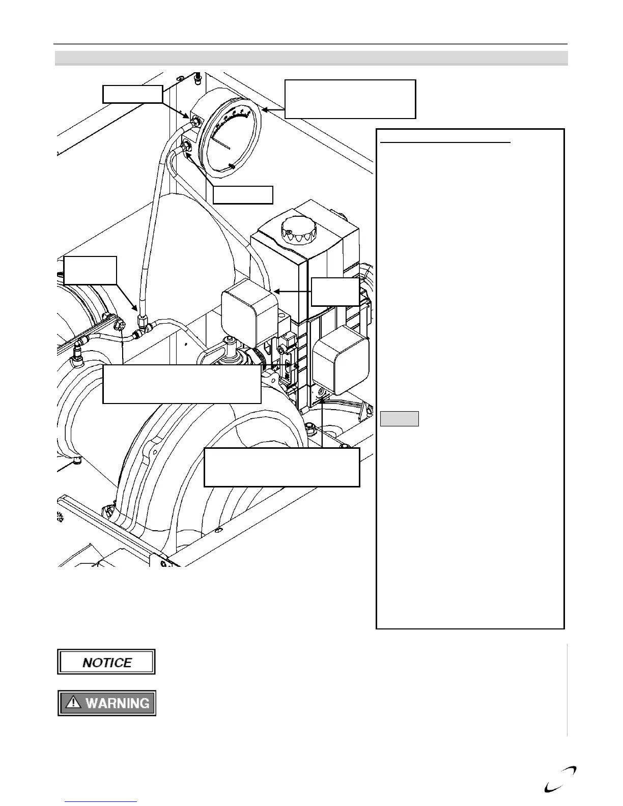
2) Installation – with the burner off,
remove the caps from the pressure
tappings. Connect the Feedback
Pressure Tapping to the Positive (+) port
of the manometer; connect the Manifold
Pressure Tapping to the Negative (-)
port of the manometer. Verify that the
manometer is reading zero – zero the
meter if necessary.
3) Calibrate Combustion – operate burner
to maximum modulation rate (seeTable
9-2), ensuring gas line pressure is
maintained above 4 inches w.c.; set
combustion according to Table 9-1 using
the Throttle Screw – record CO
2
value.
4) Set Offset – operate burner to minimum
modulation rate (see Table 9-2); set
offset pressure according to Table 9-1
using the Offset Adjustment Screw.
NOTICE: Since the Manifold Pressure
Tapping is connected to the Negative (-)
port of the manometer, a negative Offset
Pressure will read positive; e.g., to
achieve an offset pressure of -0.03,
manometer will read +0.03.
5) Verify Combustion – with the burner
remaining in operation at the minimum
modulation rate, measure combustion
and compare to readings obtained
during maximum modulation – CO
2
must
be 0.5 to 1.0% lower at minimum
modulation. If readings are out of
tolerance – CONTACT NTI FOR
ASSISTANCE.
6) Complete Test – shutdown the burner,
remove the manometer tubing and
reinstall the factory caps on Offset
Pressure Tappings.