Installation & Operation Manual│ FTG
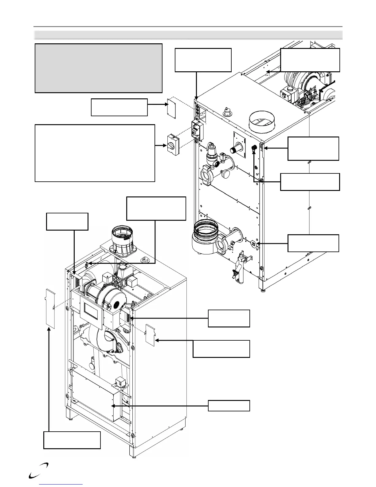
Figure 12-1 Wiring Terminal Access
Field wiring enters the back of the boiler through
strain reliefs/grommets, then is routed internally
via chase-ways to the junction boxes located at
the front of the boiler. Secure internal field wiring
to the chase-way using the factory supplied wire
supports. Field wiring entering the junction boxes
must pass through the factory supplied grommets.
Line Voltage Wiring
Strain Reliefs
(field supplied)
Low Voltage
Wiring Grommets
(factory supplied)
Access Cover – for
securing stain reliefs
Power Disconnect Switch
(FTG 2200/2400 illustrated)
- For FTG 2200/2400, remove cover and
connect 4-wire 3Ph power supply to switch,
as per Figure 12-2
- For FTG 600-2000, route 120V power supply
through strain reliefs, and terminate at the
line voltage Junction Box, as per Figure 12-2
Ethernet Connection
(optional kit required)
Condensate
Pump Receptacle
Field Wiring Chase-
way to Junction Box
(line voltage)
Junction Box Cover
(line voltage)
Junction Box
(line voltage)
Junction Box
(low voltage)
Junction Box Cover
(low voltage)
Field Wiring Chase-
way to Junction Box
(low voltage)