FTG │Installation & Operation Manual
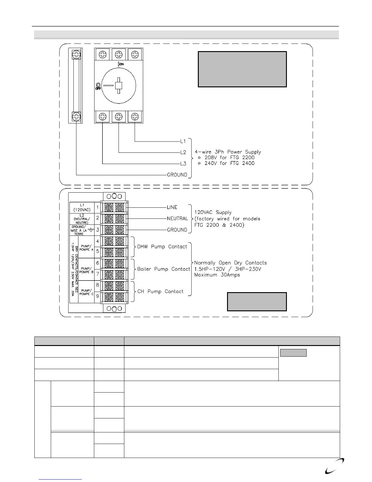
Figure 12-2 Line Voltage Field Wiring
Table 12-1 Line Voltage Field Wiring Connections
Location for connecting line wire of 120V power supply.
NOTICE: 120V
power supply is factory
wired for models FTG
2200 & 2400.
Location for connecting neutral wire of 120V power supply.
Location for connecting earth ground.
Non-Powered
(Dry Contacts)
DHW Pump Relay – Normally Open Dry Contact for DHW circulator; contact closes
during a demand for DHW. Maximum rating is 1.5HP @ 120V, 3.0HP @ 240V, or
30A.
Boiler Pump Relay – Normally Open Dry Contact for Boiler circulator; contact closes
during all demands. Maximum rating is 1.5HP @ 120V, 3.0HP @ 240V, or 30A.
CH Pump Relay – Normally Open Dry Contact for Central Heating circulator;
contact closes during a demand for CH. Maximum rating is 1.5HP @ 120V, 3.0HP @
240V, or 30A.
LINE VOLTAGE
JUNCTION BOX
3PH DISCONNECT SWITCH
(FTG 2200/2400 ONLY)
Located at the back of the
boiler; see Figure 12-1