Cascade Instructions │ Vmax I&O Manual
Labeling - Label all wires prior to disconnecting them when servicing controls. Wiring
errors can cause improper and dangerous operation. Failure to follow instructions may
result in property damage or personal injury.
Continuity - Before connecting the line voltage wiring, perform a continuity check
between all wires and ground to make sure that there are no electrical leaks that could
blow a fuse or damage electrical components. Also check the polarity of the line and
neutral wires. Line must measure 120VAC to ground; neutral must measure zero. Failure
to follow instructions may damage the unit.
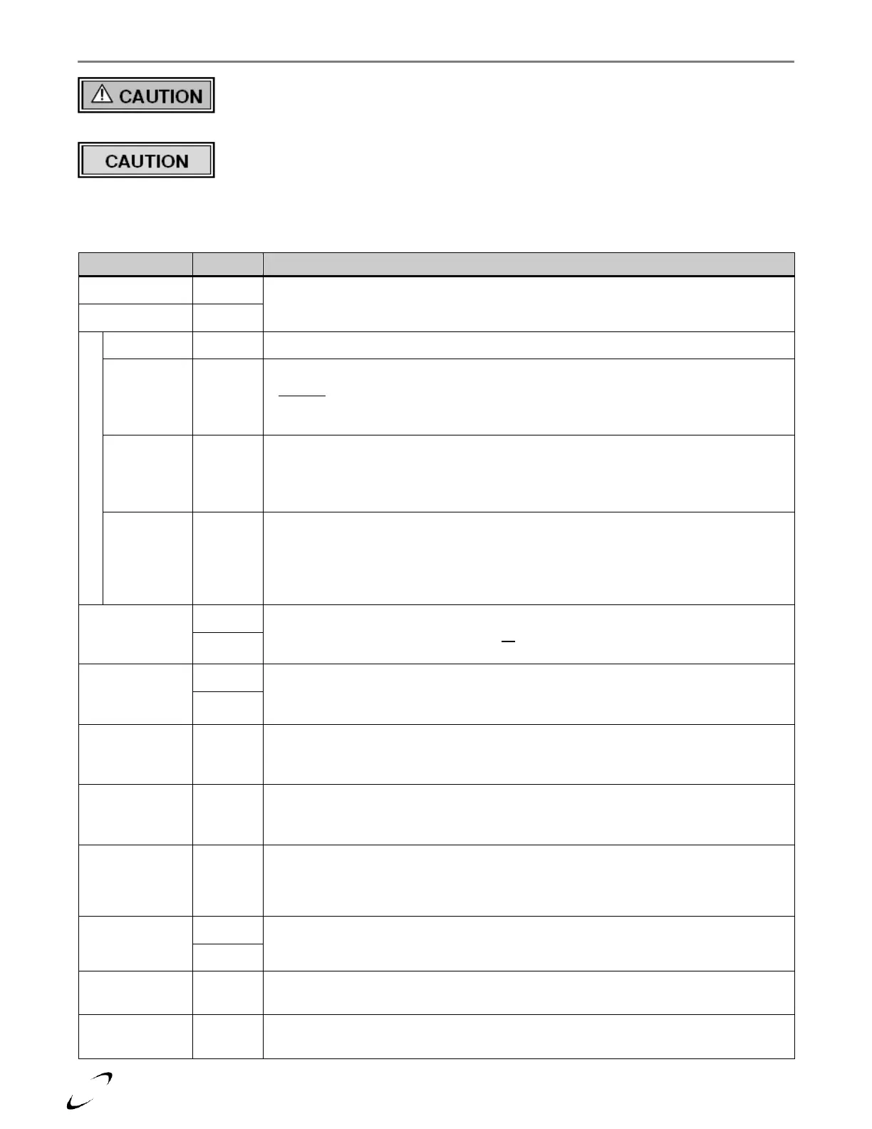
Table 12-1 Field Connections
Argus Link Communication – used to cascade up to 16 boilers, also for connection to
USB interface for PC-connection and BMS Modbus/Expansion Interface Module.
Sensor Common – Common port for field inputs SYSTEM, OUTDOOR and DHW.
System Temperature Sensor (Optional) – Wire to terminals 3 and 4 of the main boiler in
a cascade. Sensor would be installed on the system supply pipe feeding the Central
Heating system to allow accurate control of system temperature. Sensor is available from
NTI, p/n: 84010.
Outdoor Temperature Sensor – A wall mountable OD Sensor is included with each
boiler; connect to terminals 3 and 5. In a cascade, the OD Sensor only needs to be
connected to the main boiler. The use of the OD Sensor is required to allow the boiler
control to automatically infer the heat load of a central heating system.
Tank Thermostat / Sensor – Connect the contacts of a DHW Tank Thermostat, or leads
of an approved DHW Tank Sensor (NTI p/n: 84632), to terminals 3 and 6. When using a
Thermostat, set DHW mode = 2 (menu setting 2-08). When using a Sensor, set DHW
mode = 1. A Tank Sensor is factory wired to terminals 3 and 6 on Vmax Plus models
(VM110P and VM153P). See Section 17.0 for more details.
24VAC Room Thermostat Input – Connect central heat demand switch (room
thermostats or zone control end switch), or “nighttime setback” / “time of day” switch to
terminals 7 and 8. Switch must be an isolated end switch.
120VAC Safety Limit Circuit (Factory jumpered) – wire the output contacts of any
optional external limit device (i.e. LWCO) in series with terminals 9 and 10. Note: if using
an external limit device, the factory jumper must be removed.
120VAC output to the DHW circulator; powered during a demand for DHW. Total load
of DHW PUMP and BOILER PUMP must not exceed 2.6Amps. Not applicable for Vmax
Plus models (VM110P and VM153P).
120VAC output to the Central Heating circulator; powered during a demand for Central
Heat. Total load of CH PUMP and BOILER PUMP must not exceed 2.6Amps. Note: the
VM110 internal pump is wired to this output.
120VAC output to the main boiler circulator; powered during all demands. Total load of
BOILER PUMP and CH PUMP (or DHW PUMP) must not exceed 2.6Amps. Note: the
internal pump of models VM110P, VM153 and VM153P is factory wired to this output.
Location for connecting neutral of the power supply and all circulators.
Location for connecting line voltage of the power supply. Note; most installation codes
require the installation of a service switch to break line voltage to the appliance.
Location for connecting earth ground and for grounding all circulators.