EasyManua.ls Logo

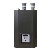
NTI Trinity Ti 150 User Manual

NTI Trinity Ti 150
38 pages
To Next Page IconTo Next Page
Page #1 background imageLoading...
Page #1 background image
1.0 SPECIFICATIONS..................................................................................................2
1.1 HIGH ALTITUDE OPERATION..................................................................................2
2.0 INSTALLATION REQUIREMENTS ...................................................................2
3.0 VENTING .................................................................................................................4
3.1 VENT PIPE MATERIAL ............................................................................................4
3.3 VENTING RULES AND GUIDELINES .........................................................................7
3.4 VENTING CLEARANCES ..........................................................................................7
4.0 CONDENSATE DRAIN..........................................................................................9
5.0 INSTALLING GAS PIPING...................................................................................9
5.0 INSTALLING GAS PIPING.................................................................................10
5.1 INSTALLATION......................................................................................................10
5.2 TESTING AND SETTINGS ........................................................................................10
6.0 HEATING SYSTEM PIPING...............................................................................12
6.1 PRIMARY LOOP PLUMBING...................................................................................13
6.2 SECONDARY LOOP HEATING SYSTEM ..................................................................16
6.2.1 Multiple Zones using Zone Valves.............................................................16
6.2.2 Multiple Zones using Pumps......................................................................16
6.2.3 Multiple Zones with Different Temperatures............................................17
6.3 DOMESTIC COMBI SYSTEM...................................................................................18
7.0 WIRING..................................................................................................................20
7.1 SIMPLIFIED WIRING CONNECTIONS......................................................................21
7.2 ADVANCED WIRING SYSTEMS..............................................................................22
7.2.1 Multiple 4 wire Zone Valves.......................................................................22
7.2.2 Multiple Zones with Taco Valve controller................................................23
7.2.3 Multiple Zones Pump controller................................................................24
7.2.4 Multiple Temperature Zones with Injection Pumps..................................25
8.0 SENTRY 2100 CONTROLLER ...........................................................................26
9.0 LIGHTING BOILER.............................................................................................30
9.1 INITIAL START-UP.................................................................................................30
9.2 RE-LIGHTING UNIT...............................................................................................30
9.3 TURN OFF BOILER.................................................................................................30
10.0 TROUBLE SHOOTING......................................................................................31
11.0 SEQUENCE OF OPERATION ..........................................................................34
14.0 ANNUAL MAINTENANCE AND INSPECTION............................................36
14.1 COMBUSTION CHAMBER CLEANING...................................................................36
15.0 PARTS LIST.........................................................................................................37
CAUTION:
IT IS THE RESPONSIBILITY OF THE HOMEOWNER TO
KEEP THE VENT TERMINAL CLEAR OF SNOW AND ICE.
Trinity Ti Boiler Only
VERSION DATE: 1-5-2010
Installation and
Operation Instructions
Trinit
y
Ti
This Boiler must be installed by a licensed and trained Heating
Technician; otherwise the warranty of this unit is void. Failure
to properly install this unit could cause damage to property
and injury to occupants possibly resulting in death.
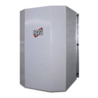
Other manuals for NTI Trinity Ti 150

Questions and Answers:

NTI Trinity Ti 150 Specifications

General IconGeneral
Fuel TypeNatural Gas or Propane
Boiler TypeCondensing
Maximum Input (BTU/hr)150, 000
AFUE95%
Efficiency95% AFUE
Operating Pressure30 psi
Gas Connection Size3/4 inch
Electrical Requirements120V AC, 60Hz

Summary

1.0 SPECIFICATIONS

1.1 High Altitude Operation

Details how boiler performance is affected by altitude, with de-rating guidelines.

2.0 INSTALLATION REQUIREMENTS

2.1 Location

3.0 VENTING

3.1 Vent Pipe Material

Specifies approved materials for exhaust and air supply piping.

3.2 Venting Configurations

3.2.1 Two-Pipe Vent Termination

Illustrates two-pipe vent termination with specific clearances and methods.

3.2.2 Concentric Vent Termination

Details concentric vent termination, noting it's not approved for Canada.

3.2.3 Ti400 Optional Vent Termination Kit

3.2.4 Roof Venting

3.3 Venting Rules and Guidelines

3.4 Venting Clearances

3.5 Determining Vent Lengths

3.6 Outdoor Horizontal Venting

4.0 CONDENSATE DRAIN

5.0 INSTALLING GAS PIPING

5.1 Installation

Details gas piping installation steps and references applicable codes.

5.2 Testing and settings

Details line pressure requirements and combustion testing procedures.

Setting Combustion

6.0 HEATING SYSTEM PIPING

6.1 Primary Loop Plumbing

Low Water Cutoff / Flow Switch

Primary Loop For Heating Model

Primary Loop For Combi Model Only

6.2 Secondary Loop Heating System

6.2.1 Multiple Zones using Zone Valves

Illustrates piping for multiple zones controlled by zone valves.

6.2.2 Multiple Zones using Pumps

Illustrates piping for multiple zones controlled by individual pumps.

6.2.3 Multiple Zones with Different Temperatures

6.3 Domestic Combi System

Domestic Hot Water Features

Anti-Scald Valve

Details the installation and setting of the anti-scald valve.

Hard Water

Addresses the impact of hard water and necessary precautions.

Cleaning

Provides instructions for cleaning heat exchangers.

Combi Limitations

Outlines limitations of the Combi system for domestic hot water.

Procedure for Setting up Domestic Hot Water

Step-by-step guide for setting up domestic hot water flow and temperature.

7.0 WIRING

7.1 Simplified Wiring Connections

7.2 Advanced Wiring Systems

7.2.1 Multiple 4 wire Zone Valves

Wiring diagram for a multi-zone system using 4-wire zone valves.

7.2.2 Multiple Zones with Taco Valve controller

7.2.3 Multiple Zones Pump controller

7.2.4 Multiple Temperature Zones with Injection Pumps

8.0 SENTRY 2100 CONTROLLER

8.1 Sentry 2100 Display

Explains the meaning of lights and indicators on the Sentry 2100 controller.

8.2 Sentry 2100 Operation

8.3 Setting the Sentry 2100

8.3.1 Sentry 2100 Menu

8.3.2 Calculating Outdoor Reset Curve (RES)

8.4 Outdoor Sensor (10K)

9.0 LIGHTING BOILER

9.1 Initial Start-up

Step-by-step guide for the initial powering and startup of the boiler.

9.2 Re-lighting Unit

Instructions for safely re-lighting the boiler if it goes out.

10.0 TROUBLE SHOOTING

ER1 On Display

Error code ER1: 'Water Temperature Excessive', with solutions.

ER2 On Display

Error code ER2: 'Water Sensor Short Circuit', with solutions.

ER3 On Display

Error code ER3: 'Water Sensor Open Circuit', with solutions.

ER4 On Display

Error code ER4: '24V Limit Error', with solutions.

ER5 On Display

Error code ER5: 'DHW Time-Out', with solutions.

ER6

Error code ER6: 'Flame Lock Out', with solutions.

ASO Indicates that the Air Switch is Open

ASC Indicates that the Air Switch is Closed

Two Flashes on Fenwal

Three Flashes on Fenwal

Boiler will not stay lit

Boiler bangs or hisses

Boiler Lights rough or pulsates

Fan appears to be creating a noise in the house

Thermistor Curves

11.0 SEQUENCE OF OPERATION

12.0 WIRING SCHEMATIC

13.0 INSTALLATION CHECKLIST

Start-up

Steps to follow for the initial startup and testing of the boiler.

Operational Checklist

Checks to perform to ensure proper operational parameters after startup.

Before Leaving

Final checks and homeowner information before leaving the installation site.

14.0 ANNUAL MAINTENANCE AND INSPECTION

14.1 COMBUSTION CHAMBER CLEANING

Procedure for inspecting and cleaning the combustion chamber.

15.0 PARTS LIST

Model Ti400

Related product manuals