17
Zone 3
High Temp.
Tempering valve
Zone 2
Med. Temp.
Zone 1
Low Temp.
Pumps sized to each
zones flow and head
requirements
Primary
Loo
Max. 12” apart
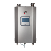
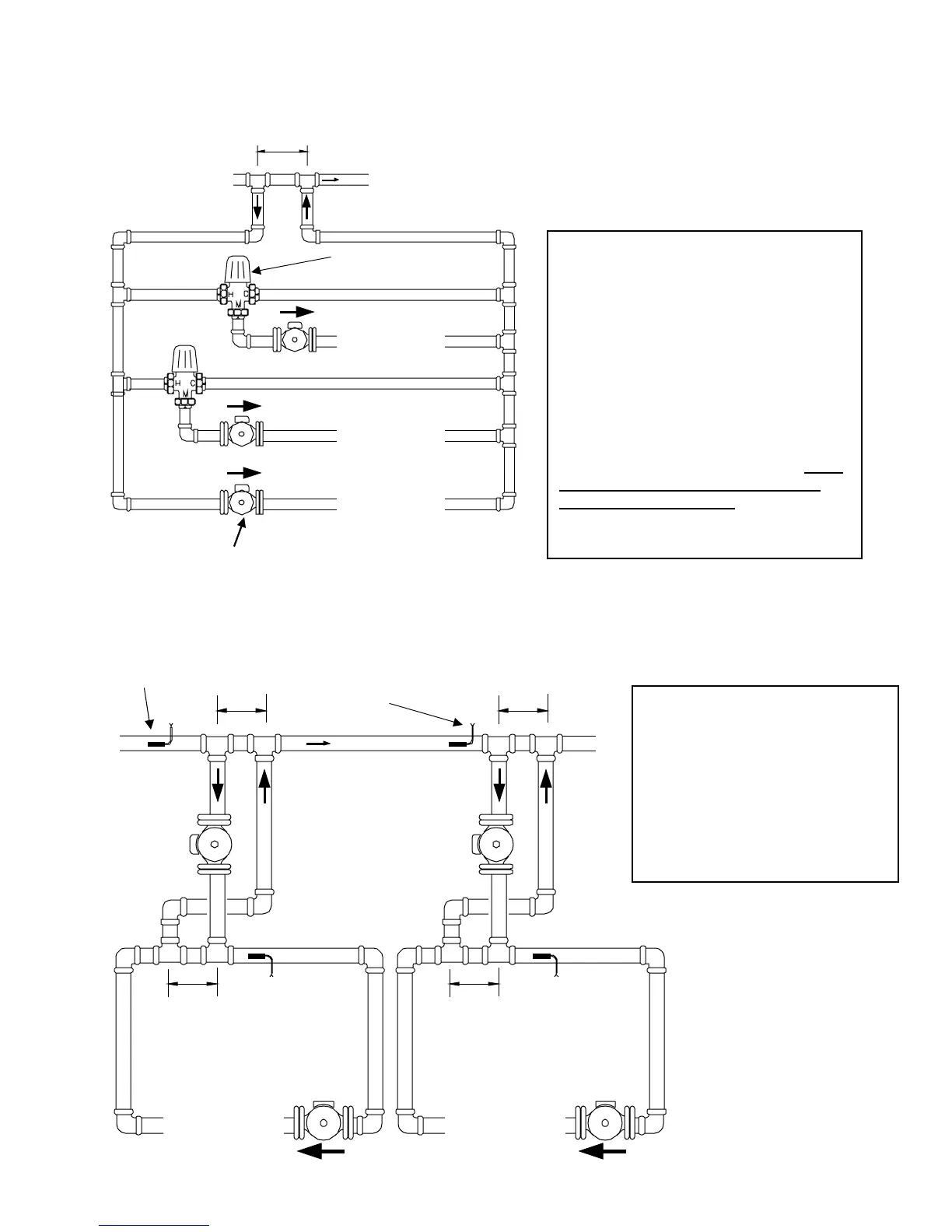
6.2.3 Multiple Zones with Different Temperatures
Using pumps and tempering valves
Using Injection pumps
Loop 1
High
Temp.
Injection
Pump
Primar
loo
Max. 12” apart
Max. 12” apart
Max. 12”
apart
Max. 12”
a
art
Loop 2
Low
Temp.
Injection
Pump
Loop Pumps sized to each loops flow and head requirements
Boiler sensor #2
(Lo Temp.)
Boiler sensor #1
(Hi Temp.)
Mix sensor #1
(Hi Temp.)
Mix sensor #2
Lo Temp.)
See figure
7.2.3 “Multiple Zones using pumps,
and pump controller”
By setting the tempering valves to different
settings, multiple temperatures can be
obtained.
Installer may require throttling and check
valves to correctly regulate the system.
Other configurations may work, but under
no circumstances can a mixing valve be
placed in the primary loop as overheating
of the boiler could occur.
See figure
7.2.4 “Multiple temperature Zones
using injection pump”
Installer may require throttling and
check valves to correctly regulate
the system