EasyManua.ls Logo

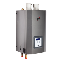
NTI Trinity TX51 User Manual

NTI Trinity TX51
84 pages
To Next Page IconTo Next Page
Page #1 background imageLoading...
Page #1 background image
Trinity Tx
Model Numbers: Tx 51 - 200
Version Date: 2014-08-28
INSTALLATION AND OPERATION
INSTRUCTIONS FOR TRINITY Tx BOILER
TABLE OF CONTENTS
1.0 INTRODUCTION ................................................................................................................ 3
2.0 SPECIFICATIONS .............................................................................................................. 6
3.0 BOILER LOCATION .......................................................................................................... 7
4.0 GENERAL VENTING ....................................................................................................... 10
5.0 VENT/AIR-INLET TERMINATION CLEARANCES ..................................................... 24
6.0 CONDENSATE DRAIN .................................................................................................... 27
7.0 INSTALLING GAS PIPING .............................................................................................. 29
8.0 LIGHTING THE BOILER ................................................................................................. 31
9.0 GAS VALVE AND BURNER SET-UP ............................................................................ 34
10.0 BOILER AND HEATING SYSTEM PIPING ................................................................... 37
11.0 DOMESTIC HOT WATER (DHW) PIPING TX151C & TX200C (COMBI) ............... 48
12.0 FIELD WIRING ................................................................................................................. 52
13.0 CASCADE INSTRUCTIONS ............................................................................................ 55
14.0 WIRING SCHEMATICS ................................................................................................... 57
15.0 INSTALLATION CHECKLIST ........................................................................................ 59
16.0 ANNUAL MAINTENANCE AND INSPECTION ........................................................... 60
17.0 DISPLAY MENU GUIDE ................................................................................................. 62
18.0 TROUBLESHOOTING ..................................................................................................... 74
19.0 PARTS LIST ...................................................................................................................... 77
HAZARD SYMBOLS AND DEFINITIONS
Danger Sign: Indicates a hazardous situation which, if not avoided, will
result in serious injury or death.
Warning Sign: Indicates a hazardous situation which, if not avoided,
could result in serious injury or death.
Caution Sign plus Safety Alert Symbol: Indicates a hazardous situation
which, if not avoided, could result in minor or moderate injury.
Caution Sign without Safety Alert Symbol: Indicates a hazardous
situation which, if not avoided, could result in property damage.
Notice Sign: Indicates a hazardous situation which, if not avoided,
could result in property damage.
This Boiler must be installed by a licensed and trained Heating
Technician or the Warranty is Void. Failure to properly install this
unit may result in property damage, serious injury to occupants, or possibly death.
NTI # 84874
NEW PRODUCT LINE
High Efficiency
Condensing Gas Boiler
H

Table of Contents

Question and Answer IconNeed help?

Do you have a question about the NTI Trinity TX51 and is the answer not in the manual?

NTI Trinity TX51 Specifications

General IconGeneral
BrandNTI
ModelTrinity TX51
CategoryBoiler
Fuel TypeNatural Gas or Propane
Efficiency95% AFUE
Modulation5:1
Input BTU51, 000 BTU/hr
Warranty12-year limited warranty

Summary

Hazard Symbols and Definitions

For Your Safety, Read Before Operating

Operating Instructions

To Turn Off Gas To Boiler

1.0 Introduction

General Installation Requirements

Boiler installation must conform to manual, local authority, and codes.

User Responsibilities

Owner must ensure annual service by qualified technician.

Installer Responsibilities

Technician must ensure installation complies with manual and codes.

Attention: Liquefied Petroleum (LP) Propane

Exhaust Vent / Air-Inlet Piping

2.0 Specifications

High Altitude Operation

Boiler capacity must be de-rated for elevations above 2000 ft.

3.0 Boiler Location

Boiler Area Ventilation Air Openings

Requirements for ventilation openings if clearances are not met.

Closet Installations

Ventilation requirements for closet installations.

Alcove Installations

Clearances and ventilation for alcove installations.

Residential Garage Installations

Specific mounting and protection requirements for garage installations.

Wall Mounting Installations

Refers to Figure 3-2 for wall mounting instructions.

4.0 General Venting

Direct Vent Installation (Best Practice)

Combustion air-inlet piped directly outdoors per codes.

Installation Using Indoor Combustion Air

Combustion air drawn from indoors via appliance area per codes.

Indoor Combustion Air - Opening Size and Location

Methods for determining opening size/location for indoor combustion air.

Outdoor Combustion Air – Opening Size and Location

Methods for providing outdoor combustion air via openings.

5.0 Vent/Air-Inlet Termination Clearances

Illustrations of Termination Clearances

Refers to Figures 5-1 and 5-2 for termination clearance details.

6.0 Condensate Drain

Condensate Trap Installation Instructions

Steps for installing the factory supplied condensate trap.

7.0 Installing Gas Piping

Installation

Guidance on gas piping requirements and sizing per codes.

8.0 Lighting the Boiler

For Your Safety, Read Before Operating

Essential safety precautions before operating the boiler.

Operating Instructions

Step-by-step procedure for lighting and operating the boiler.

To Turn Off Gas To Boiler

Steps to safely shut off the gas supply to the boiler.

9.0 Gas Valve and Burner Set-up

Gas Line Pressure

Procedure for measuring and verifying gas line pressure.

Throttle/Input Adjustment Screw

How to adjust the throttle/input screw for gas flow.

Combustion Calibration

Procedure for calibrating burner operation using a combustion analyzer.

Flue Gas Analysis and Adjustment

Mandatory step for propane conversions to ensure safe operation.

10.0 Boiler and Heating System Piping

Boiler System Preparation and Water Requirements

Steps to prepare the system and water chemistry requirements.

Near Boiler Plumbing and Components

Details on PRV, gauge, LWCO, and plumbing configurations.

System Plumbing and Air Management

Circulators, air removal, expansion tanks, and piping configurations.

11.0 Domestic Hot Water (DHW) Piping – Tx151C & Tx200C (Combi)

DHW Description of Operation

How the Combi model heats domestic hot water on demand.

DHW Limitations and Setup

Flow rate limits, cold start, preheat mode, and setup procedures.

Tx-Combi w/ DHW Storage Tank

Installation of a DHW storage tank for improved hot water delivery.

12.0 Field Wiring

Wiring Connections

General guidance on making wiring connections and using grommets.

Power Supply and Safety

Power supply requirements and electrical safety precautions.

13.0 Cascade Instructions

Communication Wiring and Boiler Setup

Wiring, managing boiler designation, addresses, rotation, and emergency setpoints.

Plumbing and System Integration

System sensor, pumps, thermostat, and tank sensor connections for cascade.

14.0 Wiring Schematics

Tx Connection Diagram

Detailed wiring diagram for the Tx boiler.

Tx Ladder-Logic Diagram

Ladder-logic diagram illustrating boiler control functions.

15.0 Installation Checklist

Installation

Checklist for completing the boiler installation steps.

Start-up

Steps for initial boiler start-up.

Operational Checklist

Checks to perform after installation for proper operation.

Before Leaving

Final checks before leaving the installation site.

16.0 Annual Maintenance and Inspection

Annual Inspection Checklist

Items to inspect at the beginning of each heating season.

Combustion Chamber Cleaning Procedure

Steps for cleaning the boiler's combustion chamber.

17.0 Display Menu Guide

Initial Power-up and Main Screen

Boiler start-up sequence and main display screen overview.

User Menu Navigation and Information

Accessing and viewing boiler operating conditions via the user menu.

Installer Menu and Settings Adjustment

Accessing and adjusting boiler parameters via the installer menu.

Lockout, Error, and Fill Status

Navigating and understanding lockout, error, and low water pressure indicators.

18.0 Troubleshooting

Boiler Servicing Precautions

Essential safety rules to follow when servicing the boiler.

Diagnosing Inoperative Boiler Issues

Steps to identify and resolve problems causing the boiler to not operate.

Troubleshooting Specific Error Codes

Guidance on interpreting and resolving error codes and operational issues.

19.0 Parts List

Tx Heat Engine and Gas Train Parts

Illustrated parts breakdown for heat engine and gas train components.

Tx Cabinet, Vent, and Air-Inlet Parts

Illustrated parts breakdown for cabinet, vent, and air-inlet components.

Tx Controls and Installation Kit Parts

Illustrated parts for controls, installation kits, and accessories.

Related product manuals