Cascade Instructions │ Tx I&O Manual
System Sensor – install a system sensor (NTI P/N: 84010) on the outlet (supply) pipe feeding the heating system,
see Figure 13-1. Wire the system sensor to terminals 3 and 4 of the Managing Boiler (left boiler in illustration).
IMPORTANT: the use of the system sensor is mandatory for proper operation of the boiler cascade system.
Outdoor Sensor – when using an outdoor sensor it must be connected to terminals 3 and 5 of the Managing
boiler (left boiler in illustration); outdoor sensors connected to non-Managing boilers will be ignored.
Boiler Pump – each boiler in the cascade must have its own circulator (see Figure 13-1) which is operated by
each respective boiler, via the BOILER PUMP output (terminal 11). The Boiler Pump must be sized according to
Table 10-4.
CH Pump – the Managing Boiler can control the Central Heating Pump via its CH PUMP output (terminal 10).
IMPORTANT: due to the limited switching capacity of the CH PUMP output, it may be necessary to use an
isolation relay to activate the CH Pump, see Table 12-1.
DHW Pump – the Managing Boiler can control the DHW Pump via its DHW PUMP output (terminal 9).
IMPORTANT: due to the limited switching capacity of the DHW PUMP output, it may be necessary to use an
isolation relay to activate the DHW Pump, see Table 12-1.
Central Heat Demand Switch (Room Thermostat) – connect to terminals 7 and 8 (T, T) of the Managing
Boiler. Switch must be an isolated end switch (dry contact). Central Heat settings are programed from the
Managing Boiler only, i.e. Installer menu settings 2-01, 2-02, 2-03, 2-04, 2-05 and 2-06.
Tank Thermostat / Sensor – connect to terminals 3 and 6 of the Managing Boiler. DHW settings are programed
from the Managing Boiler only, i.e. Installer menu settings 2-07, 2-08 and 2-09. Set DHW Mode (Installer menu
setting 2-08) according to device used; Thermostat = 2, Sensor = 1.
Boiler Address – assign a unique boiler address for each boiler in the cascade via Installer menu setting 2-20.
Managing boiler must be set = 1; other boilers must be set from 2 to 16.
Rotation Interval – establishes the time, in days, between advancements of the staging sequence of boilers in the
cascade; set via Installer menu setting 2-22 of the Managing Boiler.
Emergency Setpoint – establishes an emergency (back-up) boiler operating setpoint in the event communication
is lost between boilers, or if the system sensor is not connected. Set via Installer menu setting 2-21 of each boiler
in the cascade.
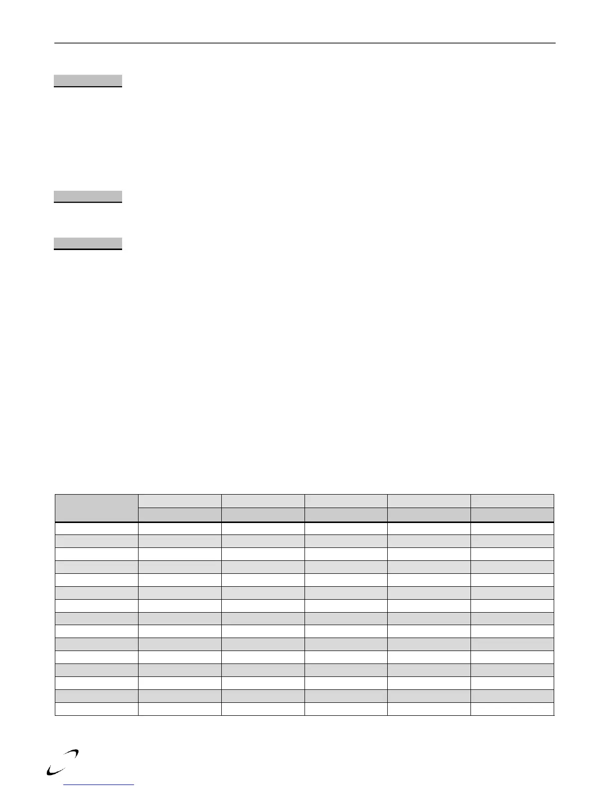
Table 13-1 Minimum Pipe Sizes for Multiple Boiler Applications
Note: Minimum pipe size based on assumed temperature rise of 25ºF at maximum firing rate.