2
27. 04. 18. Leaflet Number 671559
2.2 Electrical connection
With the unit fixed in position and working from underneath
the installation bring the external wiring through the chosen
rubber cable entry grommet (two either side, see figure 2).
The unit must be Earthed.
Installation and Maintenance MEV-DC2 Continuous Mechanical Extract Ventilation Units
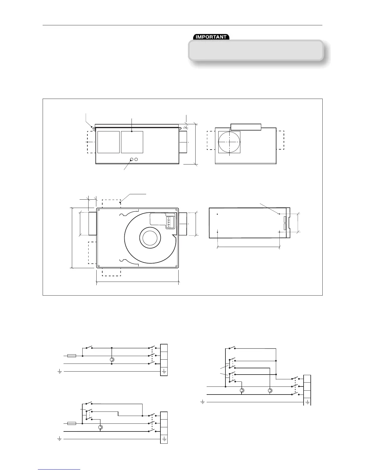
490
350
331
Bracket fixing 4 holes 7.5 dia.
VIEW WITH ACCESS PANEL REMOVED
SIDE VIEW
Cable entry 20mm
MOUNTING BRACKET TOP VIEW
END VIEW
50
Mounting bracket
Single screw unit fixing
Do not use
125 dia.
125 dia.
Alternative spigot
positions
3.0 Dimensions
Figure 4. Dimensions in mm.
Unit serving Kitchen and Bathroom
Unit serving Bathroom only
SL
L
N
Optional lamp
L
N
Fuse 2A
Mains
230V
50Hz
3 Pole
isolator
Fan unit
Remote/light switch
SL
L
N
Fan unit
3 Pole
isolator
Room light
L
N
Fuse 2A
Mains
230V
50Hz
Kitchen switch
Light switch
(Double pole)
4.0 Electrical Wiring (basic)
Unit serving Kitchen and two Bathrooms
SL
L
N
3 Pole
isolator
Room lights
L
N
Mains
230V
50Hz
Kitchen switch
Light switches
(Double pole)
Figure 5.
All field wiring and switches by others.
Isolation - Before commencing work make sure
that the unit, and Nuaire control are
electrically isolated from the mains supply.


 To Next Page