Type
DPS = Digital Pressure Switch
DVS = Digital Vacuum Switch
Output Type
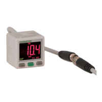
280P = PNP Digital Output Only
280N = NPN Digital Output Only
Example: DPS280PNQ8 = Digital Pressure Switch - PNP - 1/8 NPT - 8mm Pico 4 Pin w/ 2M Mating Cable
DPS 280P N Q8
Electrical Connection
Q8 = 8mm Pico Quick Connect
4 Pin w/ 2M Mating Cable
Port Type
N = 1/8 NPT Male X 10-32 F
R = 1/8 PT X M5
G = G 1/8 X M5
emale
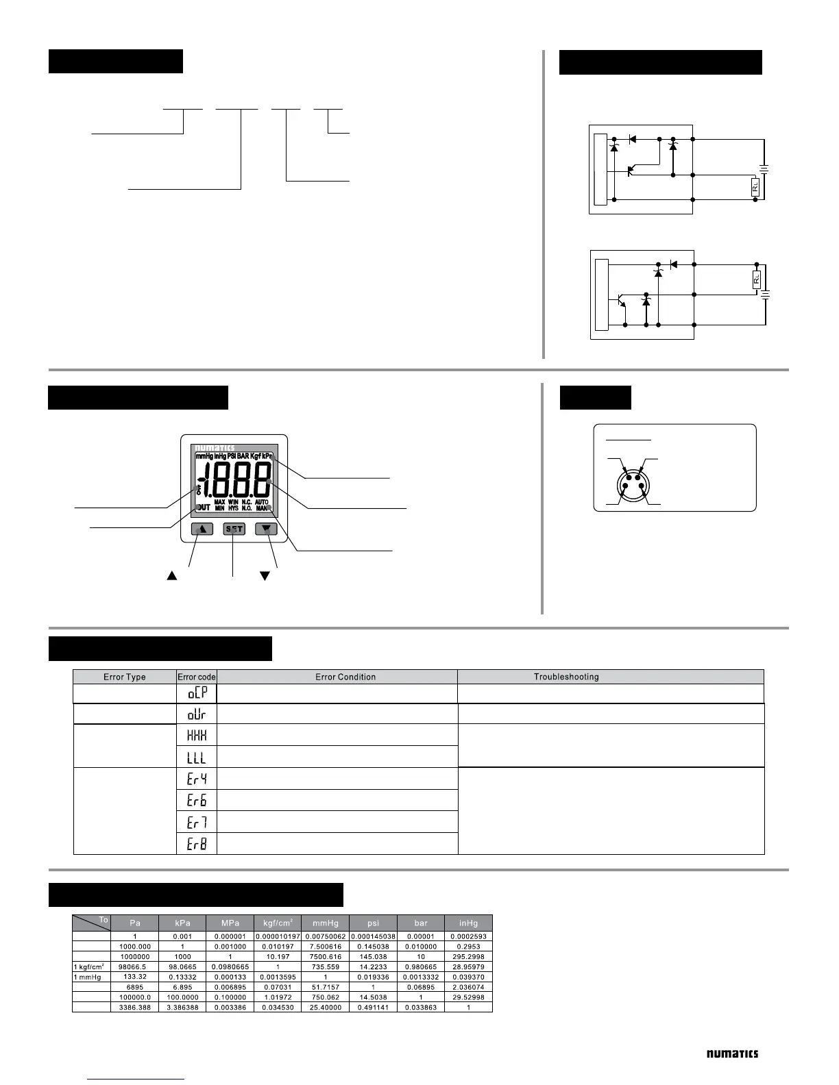
ERROR CODE INSTRUCTION
PRESSURE UNIT CONVERSION TABLE
Turn power off and check the cause of overload current or
lower the current load under 125 mA, then restart.
Excess load current error
Residual pressure error
Applied pressure error
System Error
Change input pressure to ambient pressure and perform
zero calibration again.
Adjust the pressure within operating pressure range.
Cycle power and restart. If error condition persists
please contact factory for help.
Output load current is more than 125 mA
During zero calibration, ambient pressure is over ±3% F.S.
Applied pressure exceeds the upper limit of the
operating / set pressure range.
Applied pressure exceeds the lower limit of the
operating / set pressure range.
Internal data error
Internal data error
Internal system error
Internal system error
DPS280 / DVS280 Series
2