4001 non-addressable control and indicating equipment
User Manual
1
33-0012-r11_2018-03
© 2015 ~ 2018 Ambest Electronics (Ningbo) Co Ltd. All rights reserved.
All specifications and other information shown were current at the date of publication and subject to change without notice.
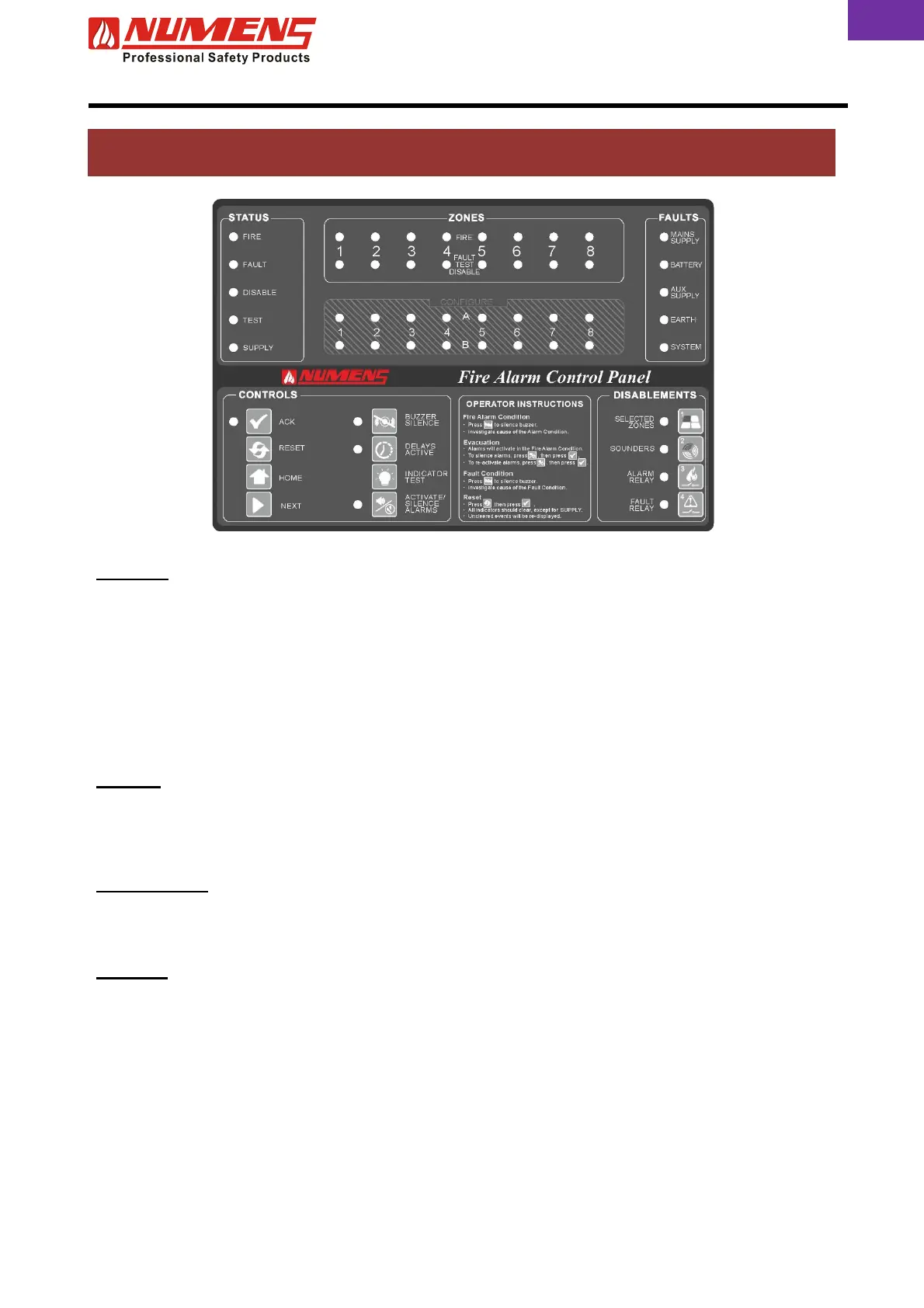
1. CONTROLS AND INDICATORS
STATUS
FIRE
Indicates the Alarm Condition. Alarm zone information will also be displayed on
the ZONE indicators.
FAULT Indicates the Fault Condition. Fault information will be displayed on the ZONES
indicators or in the FAULTS area of the control and indicating equipment,
depending on the source of the fault.
DISABLED Indicates at least one function (eg detection or Auxiliary Outputs) is disabled.
TEST Indicates the Test Condition.
SUPPLY Indicates the control and indicating equipment is active.
ZONES
FIRE Indicates the Alarm Condition within a specific detection zone.
TEST FAULT
DISABLED
Indicates when a zone is in the Test Condition, the Fault Condition or the
Disabled Condition.
CONFIGURE
A 1 ~ 8 Indicates a function during configuration at Access Level 3.
B 1 ~ 8 Indicates the zone(s) related to the configuration function at Access Level 3.
FAULTS
MAINS SUPPLY Indicates the mains supply is unavailable or less than the minimum required
voltage.
BATTERY Indicates the secondary (battery) supply or battery charger is faulty.
AUX SUPPLY Indicates a fault in the auxiliary DC output.
EARTH
Indicates an earth fault is detected in the fire detection and alarm system
transmission path wiring.
SYSTEM Indicates faults in the control and indicating equipment (including a firmware
checksum error and watchdog timer).