1211
PIPA next instructions PIPA next instructions
EN
EN
Product Use
Installation Concerns
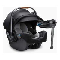
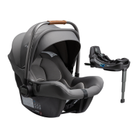
This infant carrier module is suitable for vehicle seats with i-Size ISOFIX anchor
points with the Base. (1)
DO NOT use the rearward facing enhanced child restraint systems in seating
positions where there is an active frontal airbag installed. Death or serious injury
may occur. (2) Please reference vehicle owner’s manual for more information.
DO NOT install this enhanced child restraint on vehicle seats that face sideways
or rearward with respect to the moving direction of the vehicle. (3)
It is recommended to install this enhanced child restraint on the rear vehicle
seat. (4)
DO NOT install this enhanced child restraint on vehicle seats movable during
installation.
Handle Adjustment
1 - The handle of the infant carrier module can be adjusted to 3 positions. (5)
2 - To adjust the handle, squeeze handle buttons on both sides to release it.
(6)-1
3 - Rotate handle until it clicks into any of the 3 positions. (6)-2
Installation with Base
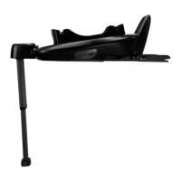
1 - Unfold the load leg from storage compartment. (7)
2 - Fit the ISOFIX guides with the ISOFIX anchor points. (8) The ISOFIX guides
can protect the surface of the vehicle seat from being torn. They can also
guide the ISOFIX connectors.
3 - Press the ISOFIX Adjust Button to adjust the ISOFIX connectors. (9)
4 - Line up the ISOFIX connectors with the ISOFIX guides, and then click both
ISOFIX connectors into the ISOFIX anchor points. (10)
Make sure that both ISOFIX connectors are securely attached to their
ISOFIX anchor points. There should be two audible clicks and the colors of
the indicators on the both ISOFIX connectors should be completely green.
(10)-1
Check to make sure the base is securely installed by pulling on the both
ISOFIX connectors.
5 - After placing the base on the vehicle seat, extend the load leg to floor (11).
When the load leg indicator shows green means it is installed correctly, red
means it is installed incorrectly. (11)-2
The load leg has 19 positions. When the load leg indicator shows red this
means the load leg is in the wrong position.
Make sure the load leg is in full contact with the vehicle floor pan.
To shorten the load leg, squeeze the load leg release button and pull the
load leg upwards. (11)-1
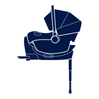
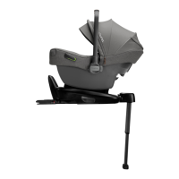
The completely assembled base is shown as (12).
The ISOFIX connectors must be attached and locked onto the ISOFIX
anchor points. (12)-1
The load leg must be installed correctly with green indicator. (12)-2
6 - To remove the base, press the secondary lock button (13)-1 first and then
the button (13)-2 on the latch connectors before removing the base from
the vehicle seat.
7 - Press the ISOFIX adjust button to fold the ISOFIX.
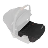
8 - Push the infant carrier module down into the base (14), if the enhanced child
restraint is secure, the side impact shield will be open and the enhanced
child restraint indicator shows green. (15) The side impact shield which is
away from the door can be closed as shown on (16) when do not use it.
Pull up on the infant carrier module to be sure it is securely latched into the
base.
9 - To release the infant carrier module, pull the enhanced child restraint up
while squeezing the infant carrier module release button. (17)
Height Adjustment
for Head Support and Shoulder Harnesses
Check that Shoulder Harness Straps are set at the proper height. Please choose
the proper pair of shoulder harness slots according to the child’s height.
Shoulder Harness Straps must be nearest to your childs shoulders (18), but
not above the shoulder line. (19)
If the Shoulder Harness Straps are not at proper height, the child might be
ejected from the enhanced child restraint if there is a crash.
Pull the head support adjustment lever (20), meanwhile pull up or push down
the head support until it snaps into one of the 7 positions. The head support
positions are shown as (21).
 Loading...