Page 3
MODEL 757SNNT
BLK
VENT
SWITCH
BLU
BLK
WHT
WHT
WHT
LIGHT
(WHITE)
GRD
VENT
(BLACK)
UNIT
SWITCH BOX
LIGHT
SWITCH
LINE
IN
BLK
RED
WHT
GRD
SCHEMATIC WIRING DIAGRAM
SWITCH BOX
LIGHT
FAN
DUAL CONTROL
(purchase separately)
WHITE
BLACK
RED
GROUND
(bare)
WIRING
PLATE
120 VAC
LINE IN
BLUE
BLACK
RECEPTACLE
(FAN)
WHITE
RECEPTACLE
(LIGHT)
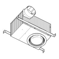
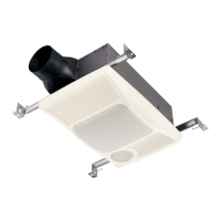
INSTALL THE HOUSING
(continued)
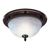
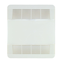
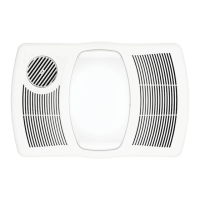
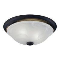
ATTACH THE GRILLE PAN AND
GLASS SHADE
INSTALL THE DUCTWORK
FLUSH
NOTE: The duct connector
has a counter-balanced
damper flap. The flap will be
CONNECT THE WIRING
1. Snap the damper/duct connector onto housing. Make sure
that tabs on the connector lock into slots in housing. Top
of damper/duct connector should be flush with top of hous-
ing.
2. Connect 4” round duct to damper/duct connector and ex-
tend duct to outside through a roof or wall cap. Check
damper to make sure that it opens freely. Tape all duct
connections to make them secure and air tight.
"open" approx. 1" when duct connector is attached to hous-
ing. This design permits insulation to be in direct contact with
fan/light housing per UL (Underwriters Laboratories) stan-
dards. The slightest backdraft, however, will close the damper
flap, preventing air from entering unit or finished space.
4. Place housing in opening so that its bottom edge is flush
with finished ceiling. Nail to joist through keyhole on both
sides. To ensure a noise-free installation, drive another
nail through the top hole of each mounting bracket.
Existing Construction
5. Additional mounting holes are provided for installations
where access from above is inconvenient or not possible.
Nail or screw housing directly to joists or framing.
ADDITIONAL
MOUNTING
HOLES
1. Thread a knurled nut onto
the short end of each shade
ring support. Install supports
from top and through holes
in grille pan.
2. Locate the grille pan over the
fan housing and connect the
wiring harness plug into
white receptacle in the fan
housing.
3. Insert rod through center
hole of grille pan. Use
washer between collar on
rod and pan. Thread rod
onto grille screw in housing,
until pan is tight against ceil-
ing.
4. Install bulbs. Use 60 Watt
(maximum), candelabra
base bulbs.
5. Install the shade ring onto
two of the supports and se-
cure each with a knurled nut.
6. Place glass shade into the
shade ring. Install the third
support and secure with a
knurled nut.
7. Restore electrical power and
check operation of the unit.
1. Wire unit following diagram
above. Run electrical cable as
direct as possible to unit. Do not
allow cable to touch sides or top of unit after installation is
complete.