4
FIGURE 5
WIRE THE HEATER
Installation work and electrical wiring must be done by a quali-
fied person(s) in accordance with all applicable codes and stan-
dards, including fire-rated construction codes and standards.
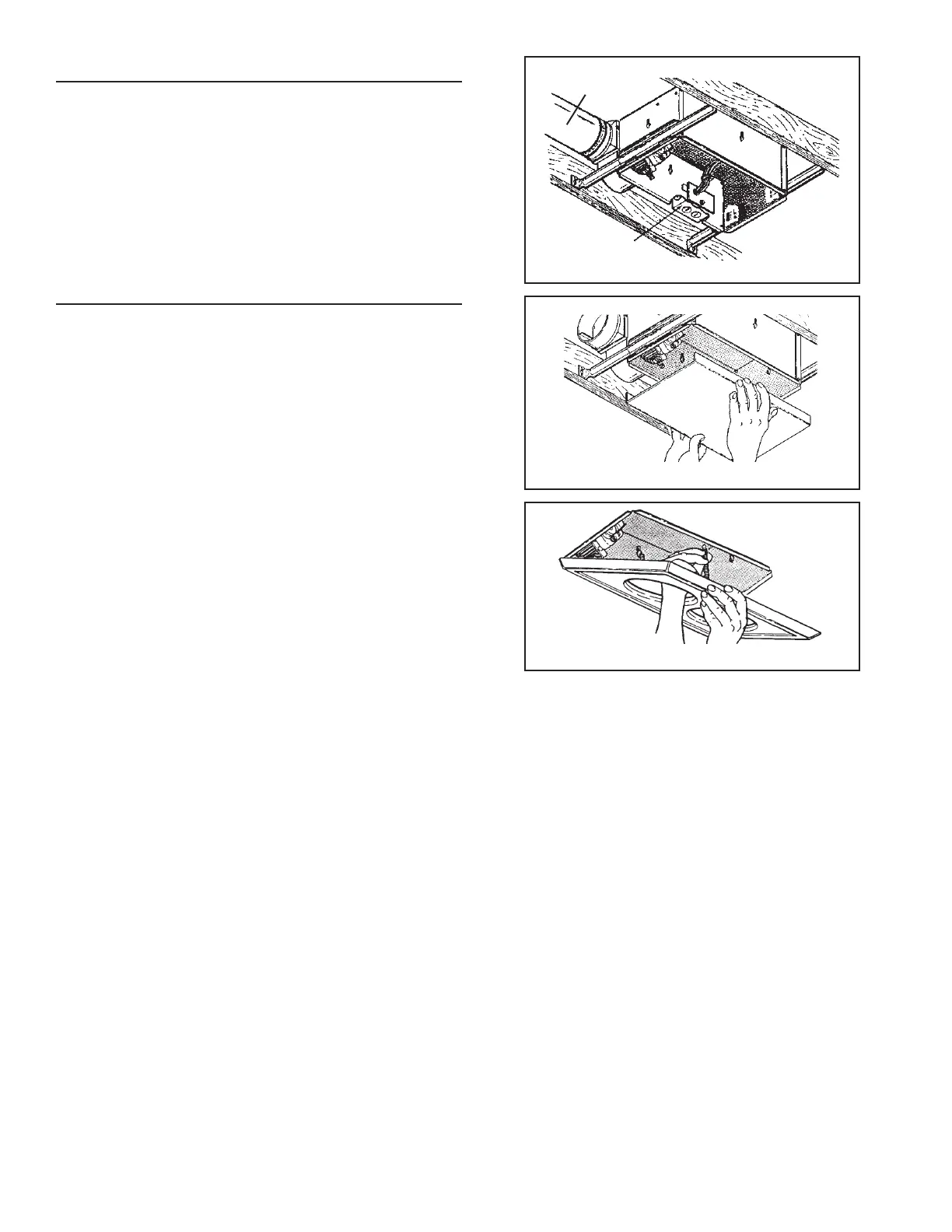
Refer to FIGURE 5
1. Remove wiring box from side of housing. Remove knockout(s)
and connect power cable(s) to wiring box using proper CSA
approved connector.
Refer to FIGURE 6 (on page 3)
2. Wire unit as indicated in appropriate diagram. Push all wiring
into wiring box and replace wiring box onto housing.
FINAL ASSEMBLY
Refer to FIGURE 7
1. Protect motor, bulb sockets and wiring from construction dust,
drywall spray, paint, etc. by using the plaster shield. Cut it from
the carton and follow directions printed on it.
2. Finish all ceiling work as necessary.
3. Remove plaster shield and check if bottom of housing is flush
with finished ceiling. If not, loosen vertical adjusting screws,
reposition housing, and retighten screws.
Refer to FIGURE 8
4. Attach grille by hooking springs onto clips on side of housing.
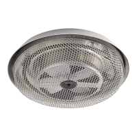
5. Install BR40 or R40-size 250W infrared bulb(s). Center grille
around bulb(s).
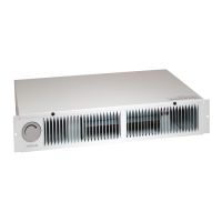
WIRING BOX
FIGURE 8
FIGURE 7
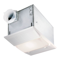
4” ROUND
DUCT