INSTALLATION, USE & CARE INSTRUCTIONS
INSTALLATION
9
PREPARE THE CABINET (CONT’D)
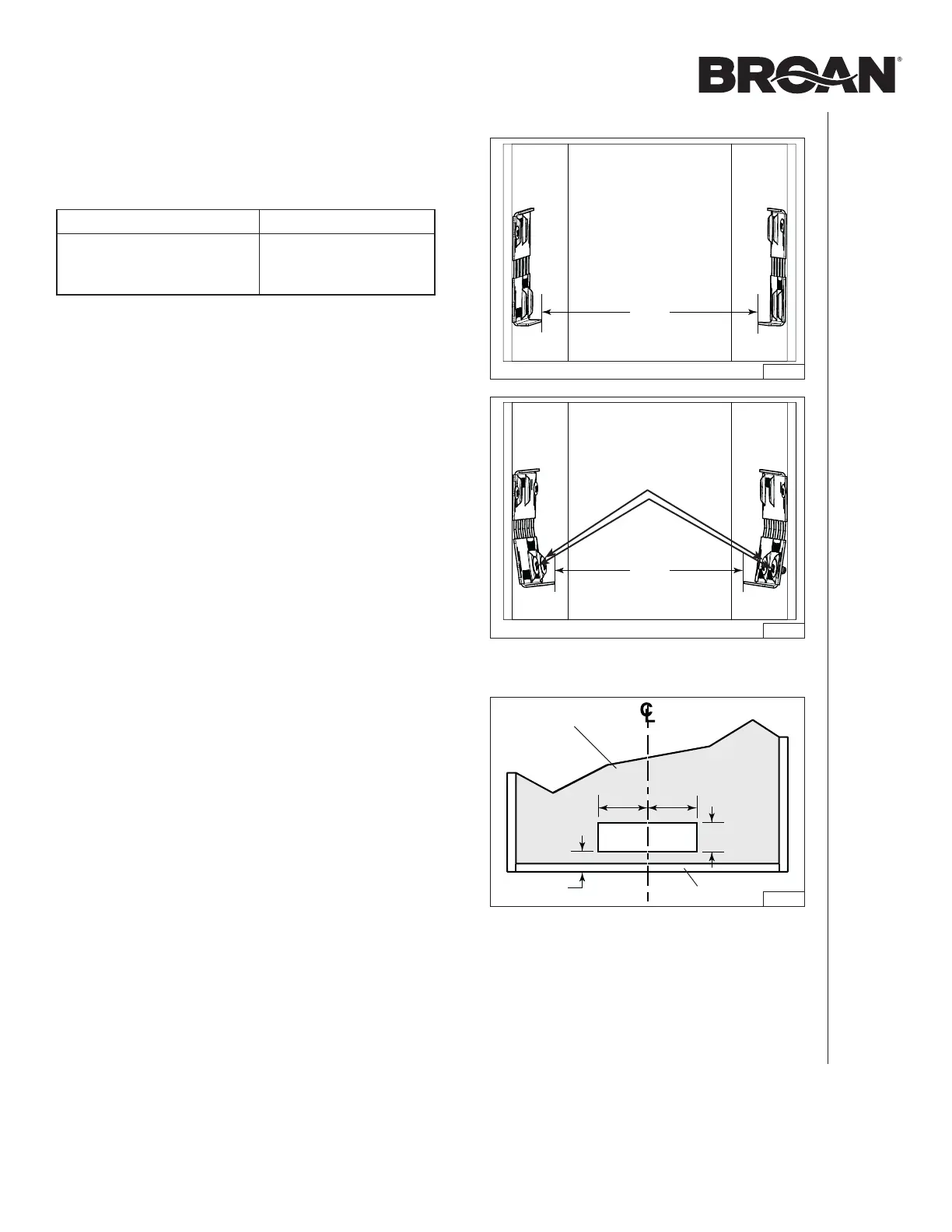
7. Measure the distance between both bottom bracket
edges (F) (FIG. 11). The table below shows the approriate
distance needed.
NARROW EDGE WIDE EDGE
F
From 19-3/8” to
< 19-9/16”
F
From 19-9/16” to
19-13/16”
If the measured distance needs to be shortened, screw two
no. 8-32 x 1/4” machine screws, in each bottom embossed
cabinet brackets hole; this will slightly bend the bottom part
of the brackets (FIG. 12). Screw both brackets until the
appropriate distance is obtained.
FIG. 13
CABINET BACK WALL
CABINET BOTTOM
HORIZONTAL EXHAUST INSTALLATION ONLY (ALL UNITS)
This powerpack insert is factory shipped to exhaust vertically;
however, it is possible to make it exhaust horizontally (3¼” x 10”
ducting only).
8. Cut the hole for the horizontal exhaust through the back
wall of the cabinet using the dimensions shown. (FIG. 13).
FIG. 11
FIG. 12
Screws in bottom
embossed holes