3. After inserting a cable into a port, the Green LED indicator will light when the
physical connection is established (that is, when the unit is powered on and a cable
is plugged into the port with the other end of the connector plugged into a
functioning port). See Networking Ports LEDs interface under the Supported
Interfaces section.
4. After plugging in a cable, lock the connector using the latching mechanism
particular to the cable vendor. When data is being transferred the Green LED will
blink.
5. Make sure not to impede the air exhaust flow through the ventilation holes. Use
cable lengths that allow for routing horizontally around to the side of the chassis
before bending upward or downward in the rack.
6. To remove a cable, disengage the locks and slowly pull the connector away from the
port receptacle. The LED indicator will turn off when the cable is unseated.
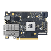
UART Cable Installation
A UART console interface is located on the DPU. Connect the supplied USB 2.0 Type-A to a
30pin Flat Socket cable from this interface to a motherboard/desired server for UART
console capabilities. For more information on the NC-SI interface, please refer to UART
Interface Connectivity.
When installing cables make sure that the latches engage.
Important
Always install and remove cables by pushing or pulling the
cable and connector in a straight line with the card.
Important