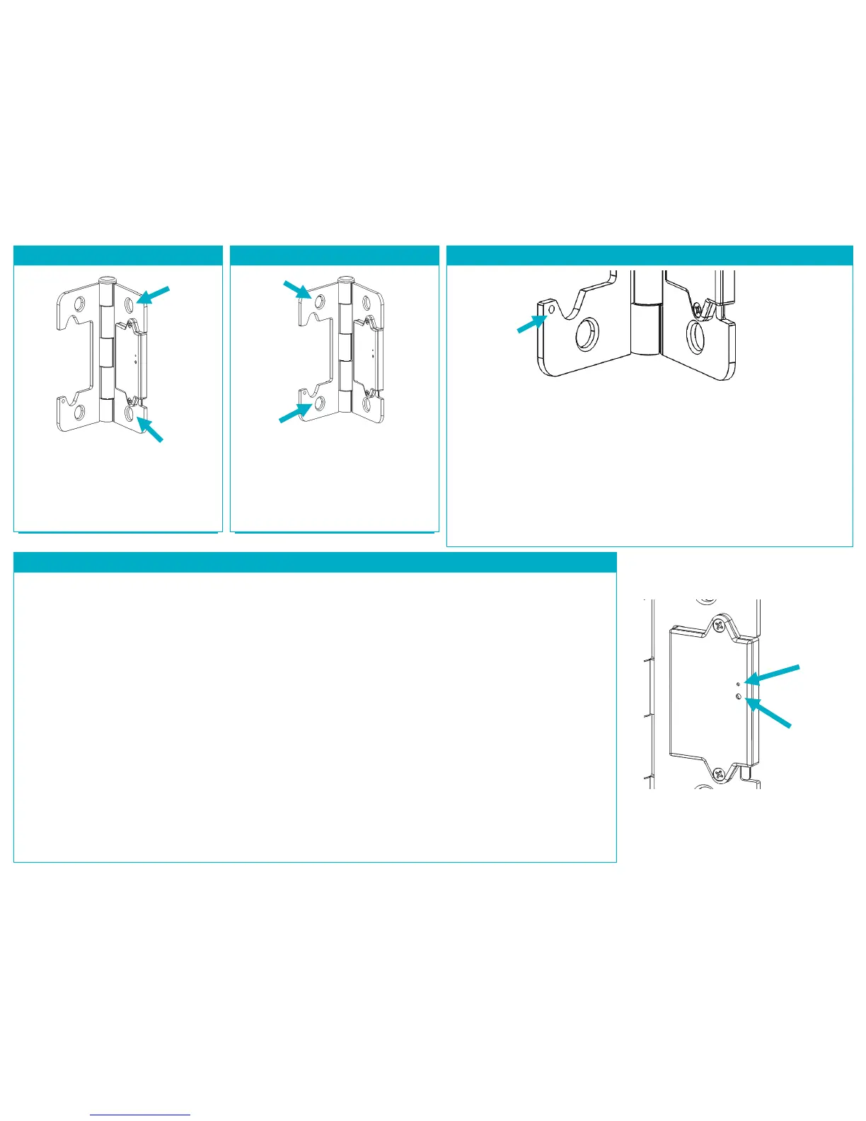
STEP 5: INSTALL ON DOOR FRAME
Mount the Door Hinge Sensor to the
door frame, insuring that it is properly
seated in the door frame recess. You
may use the screws removed from the
existing door hinge.
STEP 6: INSTALL ON DOOR EDGE
Mount the Door Hinge Sensor to the
door edge, insuring that it is properly
seated in the door edge recess. You
may need to apply pressure to your
door to bring it into alignment. You
may use the screws removed from the
existing door hinge.
STEP 7: INSTALL SET SCREW (OPTIONAL)
If the Door Hinge Sensor does not update its status as “Closed” when you close
your door, then your door may not have good alignment. You will need to
install one of the supplied set screws at the location shown above, opposite the
Contact Lever.
The supplied set screws are of two different lengths (1/8” and 3/16”) and can
simply be inserted into the set screw hole using the supplied hex key. Install the
shorter set screw first, with half its length showing, and close the door to test
the status update. Adjust the depth of the set screw using the supplied hex key
until the status shows “Closed” just as the door latches closed. Ensure the set
screw is not loose. If you cannot achive a “Closed” status, you will need to use
the longer set screw.
PRODUCT FUNCTION AND LED INDICATORS
BUTTON LED ACTION LED DESCRIPTION
2 TIMES NETWORK STATUS JOINED
NOT JOINED
RE-JOIN IN PROCESS
4 TIMES NETWORK JOIN SEARCHING FOR NETWORK
DEVICE BEING CONFIGURED
DEVICE JOINED
DEVICE FAILED TO JOIN
8 TIMES FORCED RE-JOIN RE-JOIN, SEARCHING FOR PARENT
10 TIMES NETWORK LEAVE LEAVE (IF JOINED) AND
AND DEFAULT DEFAULTS RESTORED
NO ACTION WRONG BUTTON PRESS
DEVICE BUSY
POWER UP