D
3250
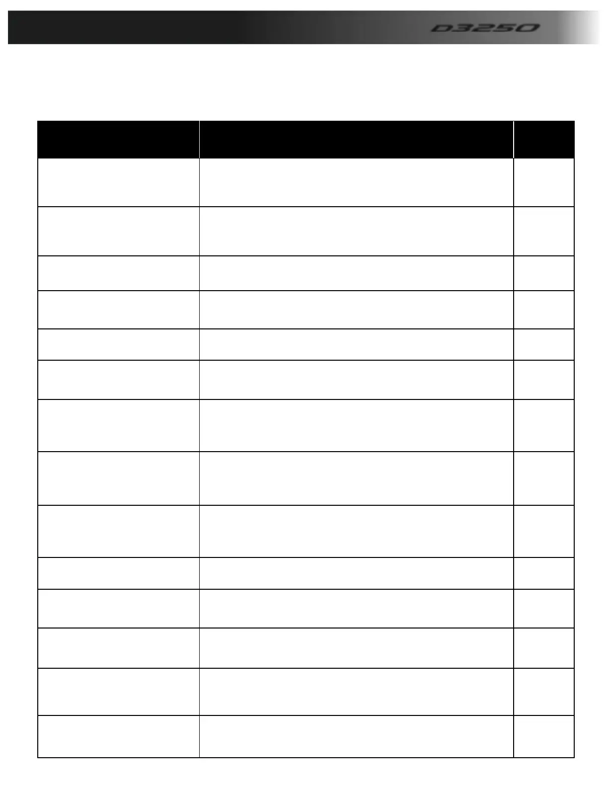
Barrier parameters
Barrier parameters Description Default
No Pass Timer
This turns on a timer that times out and lowers
The barrier if no vehicle passes through the loops
Or photocells. This timer is located in Timers.
OFF
Safety Reverse
This allows the barrier to raise back up if the loops
Or photocells are activated whilst the barrier is
Lowering.
OFF
Loop/Photocell Close
This closes the barrier once the loop or photocells
Have been activated.
OFF
Boom Lights
This turns the output on for Boom lights to operate,
The lights will turn off in the up position.
OFF
Flashing Boom Lights This enables the Boom lights to flash OFF
Slow down
This enables the barrier to slow down after a set
Time, The timer for this is located in timers.
ON
Inverter Outputs
The Plc runs the inverter via a network cable, this
Option turns on the outputs to run an inverter hard
Wired.
OFF
Raise Timeclock
This turns ON the raise timeclock which will hold the
Barrier up at set times of the day. See timeclock
Setup on page 18.
OFF
Auto Timeclock
This turns on the Timeclock that disables the auto
Loop from operating at set times of the day. See
Timeclock set up on page 18.
OFF
N/O Safety This turns the safety input into normally open OFF
Master/slave
This turns on the master/slave outputs to operate
A slave barrier from. Q6 = Raise Q7 = Lower
OFF
Traffic light This turns on the traffic light output OFF
Kerb Interlock
This turns on the kerb interlock program, see your
Supplier for connection/operation details.
OFF
2 Step logic The 2 step logic allows the raise input to lower
The barrier once raised.
OFF
Below is a table of all the parameters available to set in the barriers PLC, Please note there may be
Bespoke programs developed for certain companies where the parameters may be differ from below.