- 7 -
LAYOUTWIRING NOTE
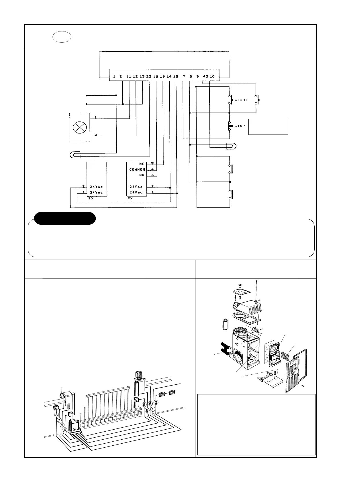
GB CONNECTION DIAGRAM
LINE 230 Vac
NEUTRAL
POSITIVE
FLASHER
COURTESY LIGHT
PHOTOCELL
INDICATOR
MAGNETIC KEY READER
KEYED SWITCH UNIT
PEDESTRIAN
START
POS. DESCRIPTION N° CABLES Min. Cross-section
1 Power cable 2 + Earth 1.5
2 Pushbutton control pannel 4 1
2 Pedestrian pushbutton 3 1
3 Keyed switch unit 3 1
4 Photocell receiver 4 1
5 Photocell transmitter 2 1
6 Flasher 2 1
7 External radio receiver 4 (+1) 1
8 Pneumatic Stop 2 1
9 Courtesy light 2 1.5
N.B.
OTHER STOP CONTACTS
MUST BE CONNECTED IN
SERIES
WARNING
Install the unit and the various devices according to the current safety standards.
Connect up with the 230 V AC mains only down-line from a differential or thermal cut-out switch.
Always separate the power cables from the control and safety cables (pushbuttons, photocells, etc.), preferably using separate sheaths.
Check the electrical connections before connecting the power supply: incorrect connections can damage the appliance.
ELECTRONIC EQUIPMENT ASX03I
TECHNICAL SPECIFICATIONS
Power supply 230Vac ± 10% 50Hz
Max. absorbed power 500 W
24 Vac accesssory max. load 300 mA
Indicator light max. power 3W (24Vac)
Courtesy light contact max. capacity 200W
Flasher fuse output 250 mA
Operating temperature -20° / +70°
RADIO
RECEIVER
ELECTRONIC
EQUIPMENT
SPARE
FUSES
EARTH
TERMINAL
MAGNETIC
STOPS