6
Installation items:
The factory only provides the main unit and the water unit; the other items in the illustration
are necessary spare parts for the water system ,that provided by users or the installer.
3.1 Installation illustration
Attention:
Please follow these steps when using for the first time
1.Open valve and charge water.
2.Make sure that the pump and the water-in pipe have been filled with water.
3.Close the valve and start the unit.
ATTN: It is necessary that the water-in pipe is higher than the pool surface.
3.INSTALLATION AND CONNECTION
Chlorinator cell
Water outlet
Pool
Valve
Water supply
Water inlet
Water pump
Sand filter
(or other type filter)
The schematic diagram is for reference only. Please check the water inlet/outlet label on the
heat pump while plumbing installation.
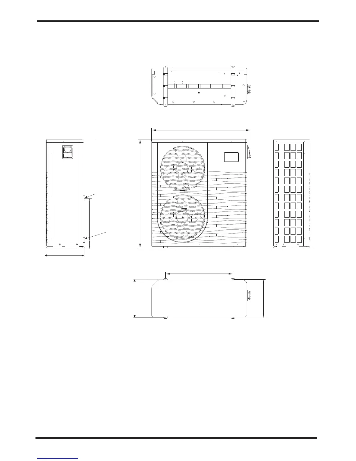
2.SPECIFICATION
5
2.2 The dimensions for Swimming Pool Heat Pump Unit
Water inlet
Φ40
Water outlet
Φ40
470
100
OASIS Ci 21/OASIS Ci 25
unit:mm
1163
1275
790
430
470
447