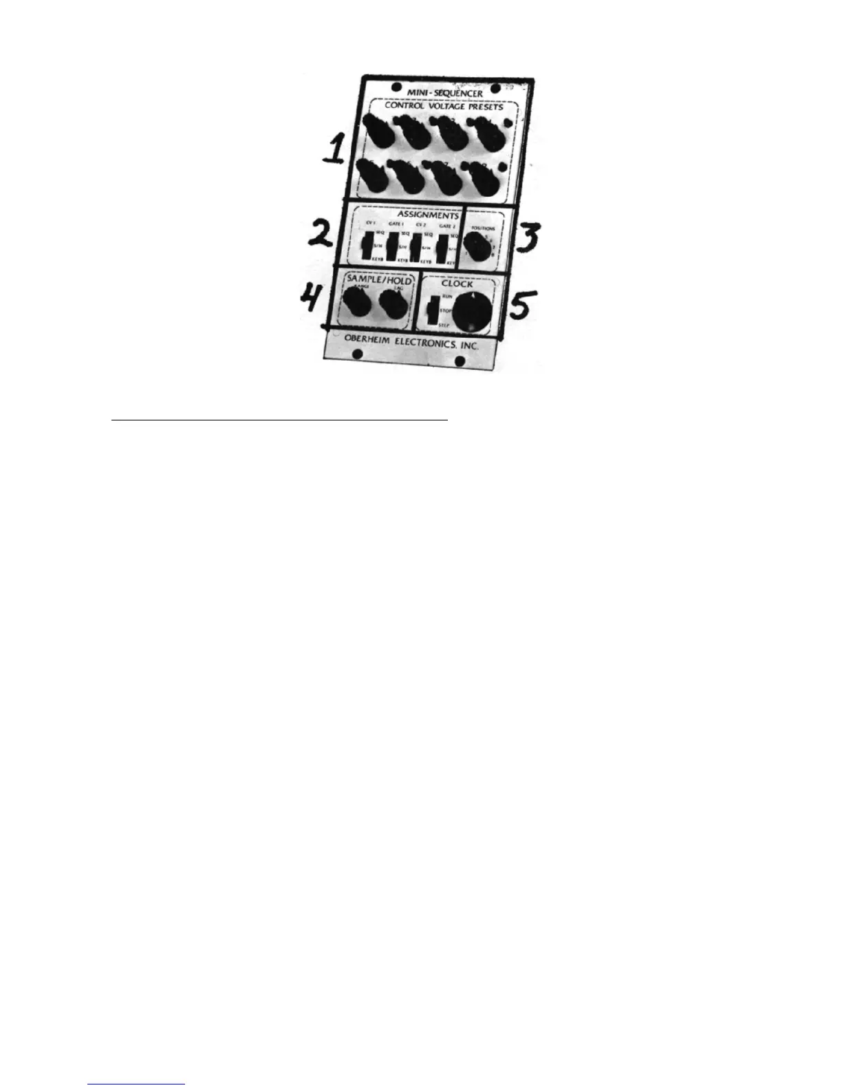
3
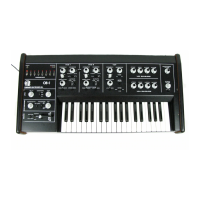
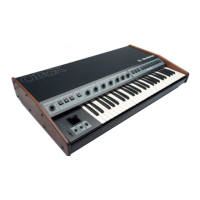
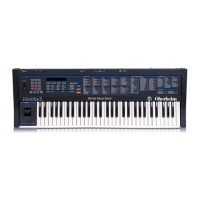
THE MINI-
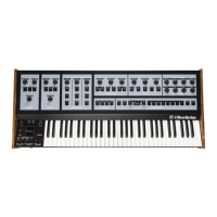
SEQUENCER AND SAMPLE/HOLD.
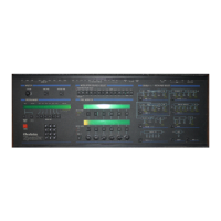
1. The CONTROL VOLTAGE PRESETS determine two different output
voltages at each of the sequencer's eight positions. Each num-
bered position in this section of the panel has two independent
concentric rotary pots. The outside pot controls the SEQUENCE
OUTPUT ONE, and the inner pot determines SEQUENCE OUTPUT TWO.
An LED at each position is illuminated when that position is
active.
2. The VOLTAGE ASSIGNMENT SWITCHES determine the source and
destination of voltages from the sequencer and sample/hold.
In
the module illustrated there are four switches. In the module
included with the 2-voice synthesizer there are three switches;
the description following applies to the three-switch version.
The first switch on the left selects the source of control
voltages and gates for VOICE MODULE ONE. In its lowest posi-
tion, voice module one will be controlled by the keyboard only,
and will not be affected by either the sequencer output volt-
ages or the sample/hold output voltages. In the center position
of this switch, voice module one will be gated by the CLOCK (#5
below) and its VCO's will be controlled by the output of the
SAMPLE/HOLD (#4 below). When the switch is in its highest posi-
tion, voice module one will be gated by the CLOCK and its VCO's
will be controlled by SEQUENCE OUTPUT ONE.
The second switch performs the same selecting function for
VOICE MODULE TWO, except that in its uppermost position the
VCO's in voice module two will be controlled by SEQUENCE OUTPUT
TWO rather than sequence output one.