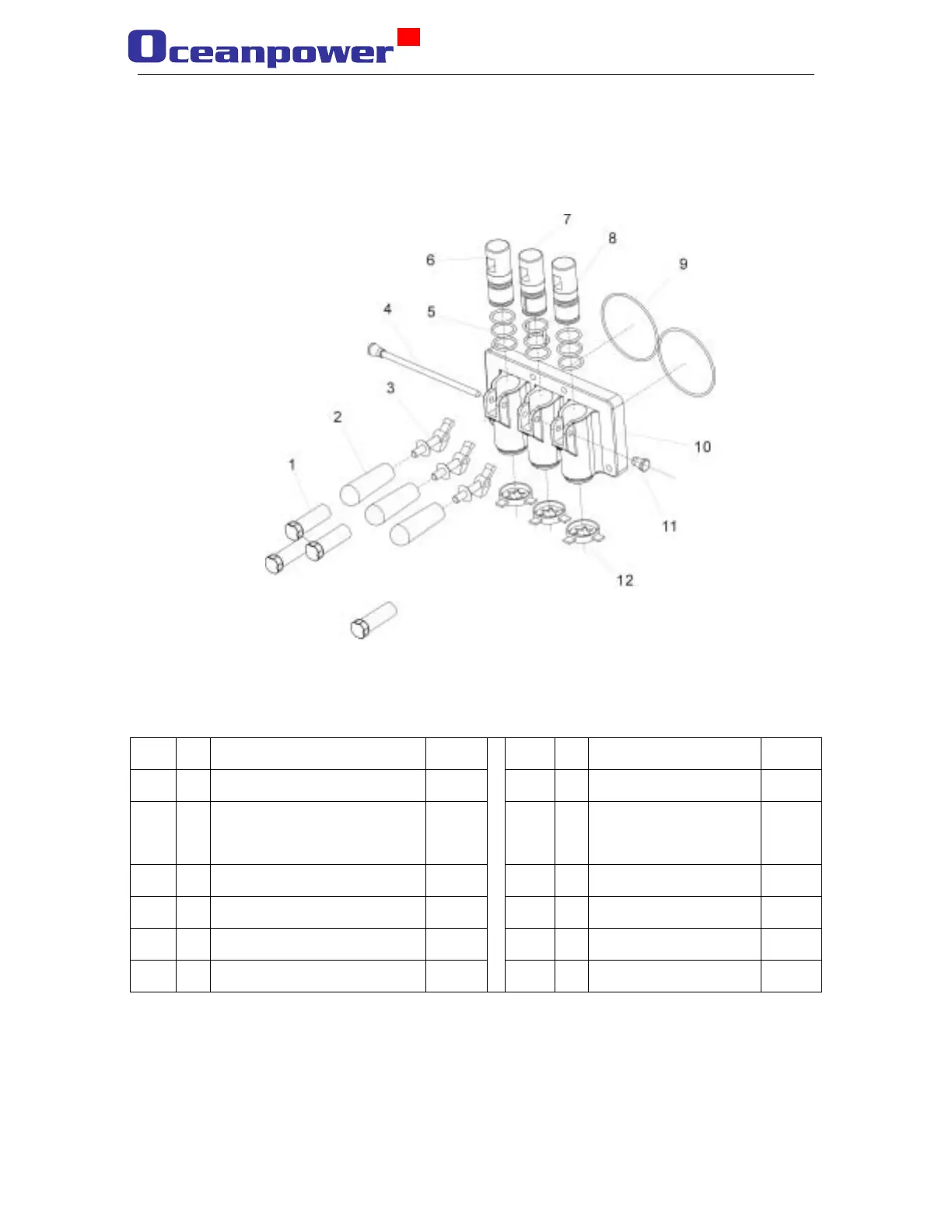
1.2.4 Discharge door assembly
icture 4: Schematic picture of the door assembly
Item Name
Quantity Item
Name
Quantity
1 Hand screw 4 7 Center draw valve 1
2 Distribution handle 3 8 Center draw valve O-
ring(φ33×3.1)
1
3 Distribution lever 3 9 O-ring(φ105×5.7) 2
4 Pivot pin 1 10 Discharge door body 1
5 Draw valve O-ring(φ33×3.1) 7 11 Pivot pin nut 1
6 Draw valve 2
12 Design cap 3
9