C-Arm Subsystem
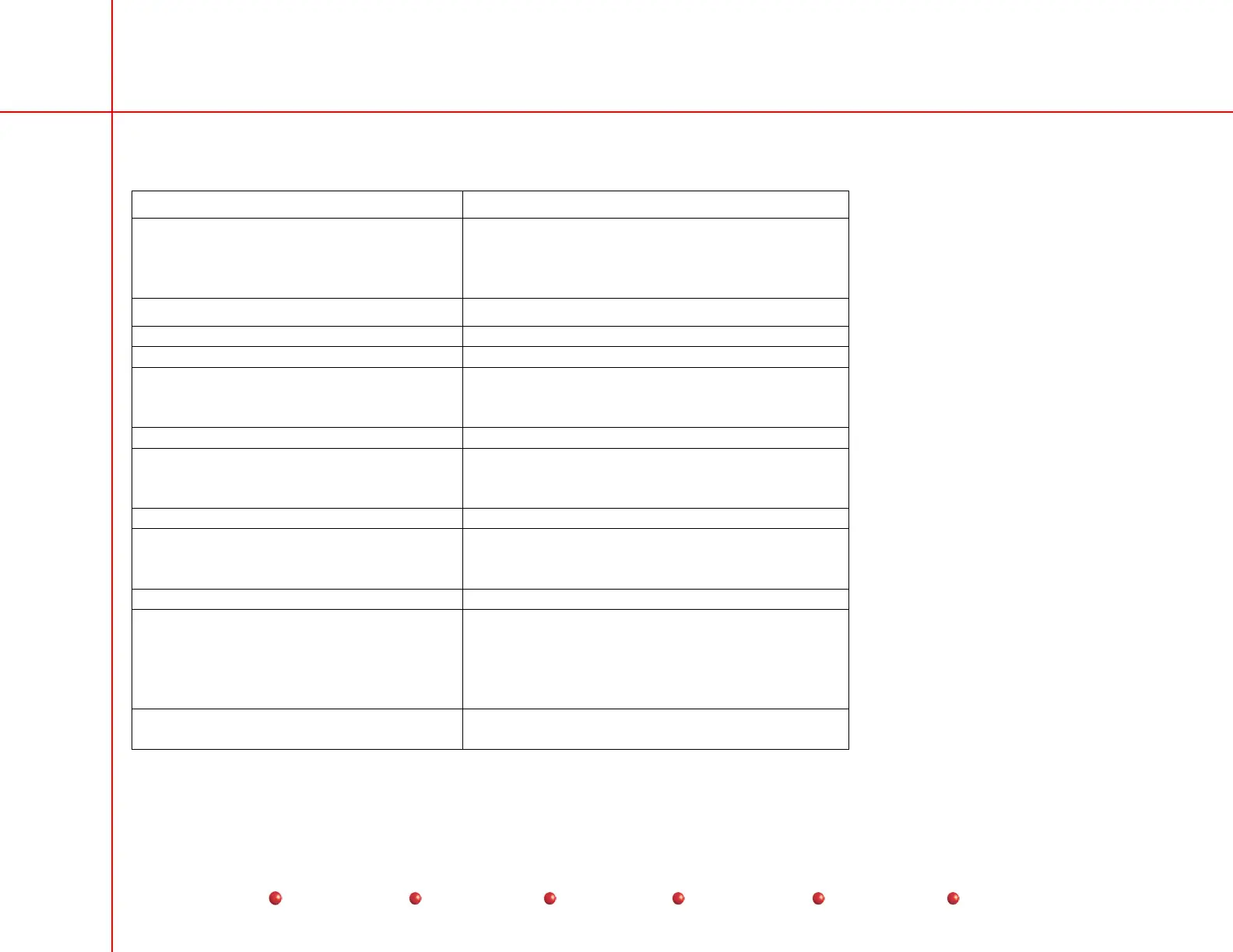
The following table lists the primary components of the standard C-Arm associated with the major assemblies shown in the
previous diagram, for the purpose of indicating physical location.
Location Major Assemblies
Control Panel Housing Assembly Left and Right Hand Control Panels
Control Panel Processor I/O PCB
Control Processor Assembly
Vacuum Fluorescent Display (VFD) Modules (2)
Camera Cover CCD Camera
Image Intensifier Image Intensifier Power Supply
Vertical Column Lift Column
L-Rotational Arm Assembly L-Rotation Mechanical Assembly
Flip Flop
Gas Shock
Collimator Cover Primary and secondary Collimator
X-ray Tube Cover Thermal Switch
Temperature Sensor
X-ray Tube
Front Top Cover Power/Motor PCB
Front Leg Cover Front Caster
Steering Chain
Cable Pushers
Right Front Cover Capacitor/Power Module
Left Front Cover Stator/Pre-charge Transformer
Multi-output Transformer (PS 2)
Capacitors, Motor AC (2)
Power/Signal Interface PCB
Power Supply, +5/+12/±15 VDC (PS1)
Cross Beam End Cap (left and right
sides)
Part of rear steering system
9
Service
Periodic Maintenance
Contents
Schematics
Illustrated Parts
Installation
 Loading...


