Diagnostics
PCB Diagnostic LEDs
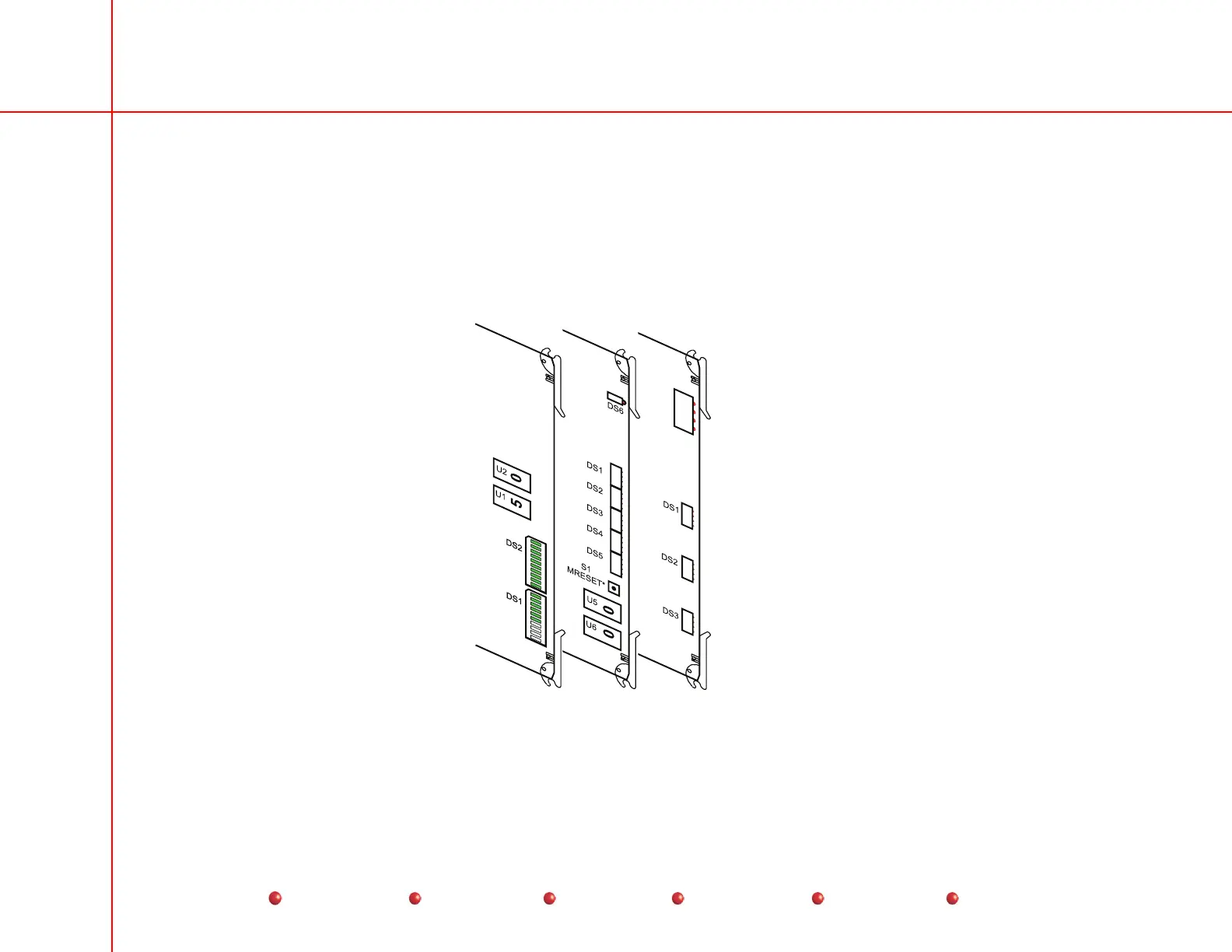
The following illustrations show LEDs on C-Arm PCBs that can be used for troubleshooting purposes. All of these PCBs reside in
the C-Arm card rack. A simplified illustration of the location of these PCBs is shown next, followed by an illustration of the LEDs
on each PCB. Some of the LEDs don’t change state during system operation. Others turn on and off with normal system activity.
Other LEDs come on only when the circuit they monitor is faulty. See the following illustrations for additional details.
Fluoro Functions PCB
X-ray Contoller PCB
HV Supply Regulator PCB
LED Locations on C-arm
29
Service
Periodic Maintenance
Contents
Schematics
Illustrated Parts
Installation
 Loading...


