Calibration
Collimator Alignment Verification
1. Attach the beam alignment tool to the image tube.
2. Fluoro in the Normal field, no collimator iris or leaves should be visible in the image.
3. Fluoro in Mag1 & Mag2, verify that no collimator iris or leaves are seen in the image
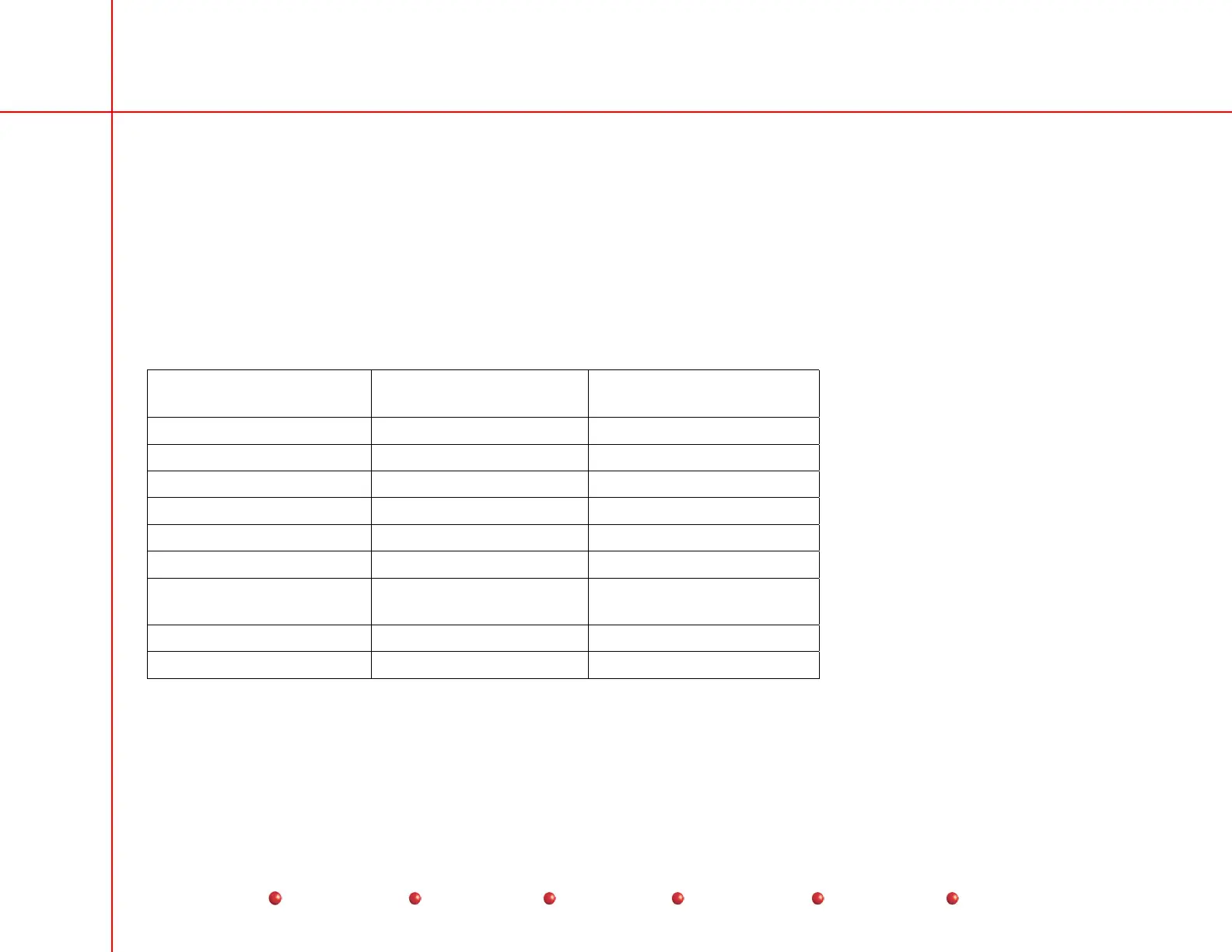
4. Measure the X & Y diameters of the image, the measured diameters must fall within the ranges listed.
5. Use the ruler marks that intersect the center of the flat portions of the collimator iris to determine the X & Y image diameters
(see the following table).
Image Tube Size Maximum Visible
Diameter
Minimum Visible Diameter
9 Inch Normal Mode 216 MM 208 MM
9 Inch Mag1 144 MM 136 MM
9 Inch Mag2 124 MM 116 MM
12 Inch Normal Mode 290 MM 283 MM
12 Inch Mag1 207 MM 199 MM
12 Inch Mag2 154 MM 147 MM
9 Normal Mode on Super
C
212 MM 206 MM
9 Mag 1 on Super C 156 MM 150 MM
9 Mag 2 on Super C 118 MM 112 MM
6. Close the collimator iris to its minimum position. Fluoro and verify that the collimated beam is smaller than the box on the
beam alignment template.
7. Move the collimator Iris and leaves without making a Fluoro exposure. Verify that the collimator preview circles and lines are
displayed on the left monitor. Fluoro and verify that the preview circles and lines, and the actual collimated image line up
56
Service
Periodic Maintenance
Contents
Schematics
Illustrated Parts
Installation
 Loading...


