Replacement
5. Locate two battery cables just above P1A and P3B. These two cables have blue connectors that connect to each other.
USING GREAT CARE TO AVOID ELECTRIC SHOCK, disconnect the cables from each other.
7. USING GREAT CARE TO AVOID ELECTRIC SHOCK, connect a current-limiting resistor (300k or so) across
Capacitor/Power module busbars to discharge high energy capacitors inside Capacitor/Power module. (Refer to
Capacitor/Power module replacement procedure in this chapter for more details.)
8. Remove Generator Driver cover and disconnect its DC fan. Tag fan connectors so you can find them later.
9. Remove and tag wires from connectors E1 and E2 on High Voltage tank.
10. Disconnect J1 from P1 on tank, and disconnect J2 from P2 on tank.
11. Follow procedure provided elsewhere in this chapter to remove Filament Driver PCB.
12. Follow procedure provided elsewhere in this chapter to remove IGBT Snubber PCB.
13. USING GREAT CARE TO AVOID ELECTRIC SHOCK, use spanner wrench to disconnect Anode cable from High Voltage
tank and immediately discharge cable to ground through an appropriate current-limiting resistance.
14. USING GREAT CARE TO AVOID ELECTRIC SHOCK, use spanner wrench to disconnect Cathode cable from High Voltage
tank and immediately discharge cable to ground through an appropriate current-limiting resistance.
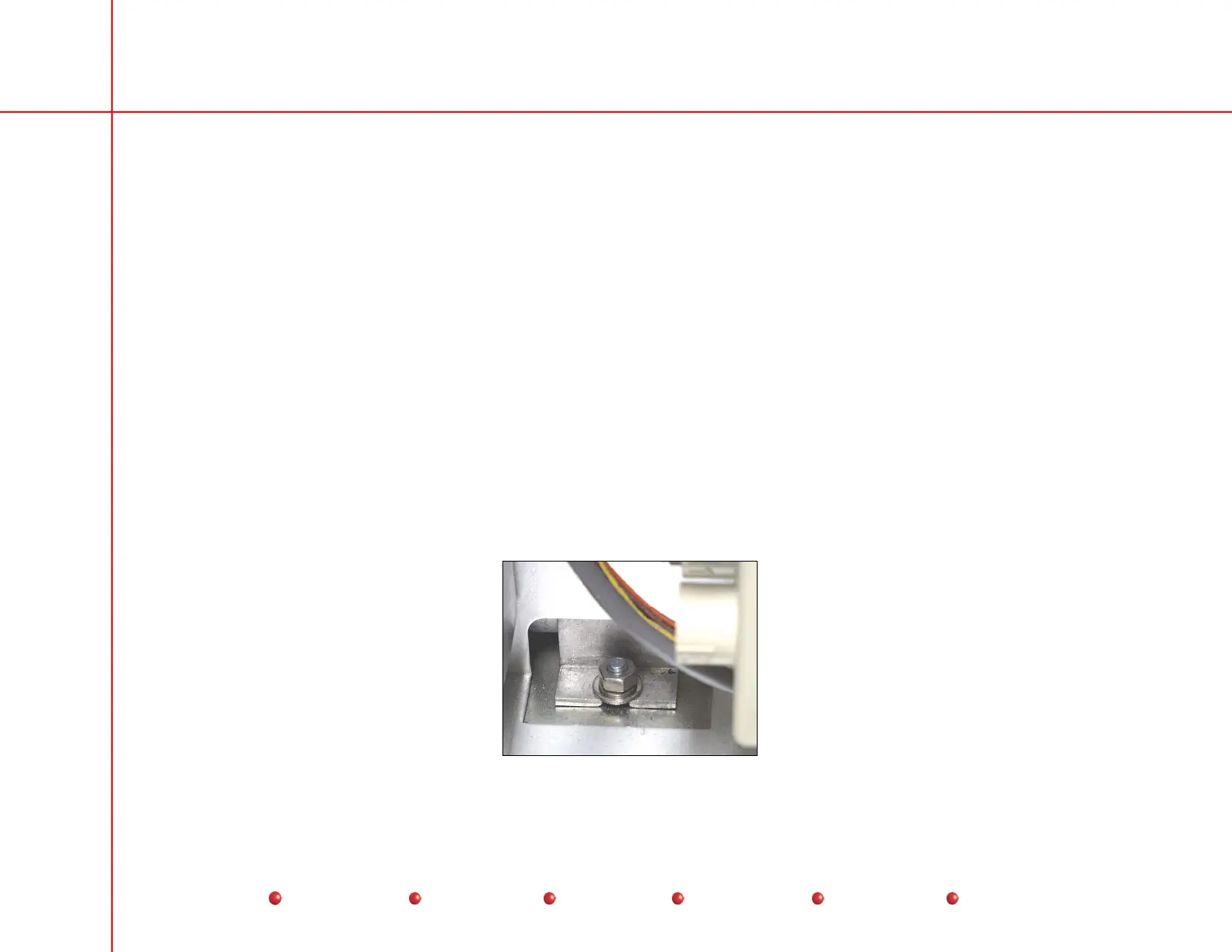
15. Remove hex nut and washers that secure left side of tank to chassis. This fastener is accessible near PS3 on the left hand
side of the chassis.
High Voltage Tank Fastener - Left Side
66
Service
Periodic Maintenance
Contents
Schematics
Illustrated Parts
Installation
 Loading...


