DC Power Distribution
±
15VDC Output
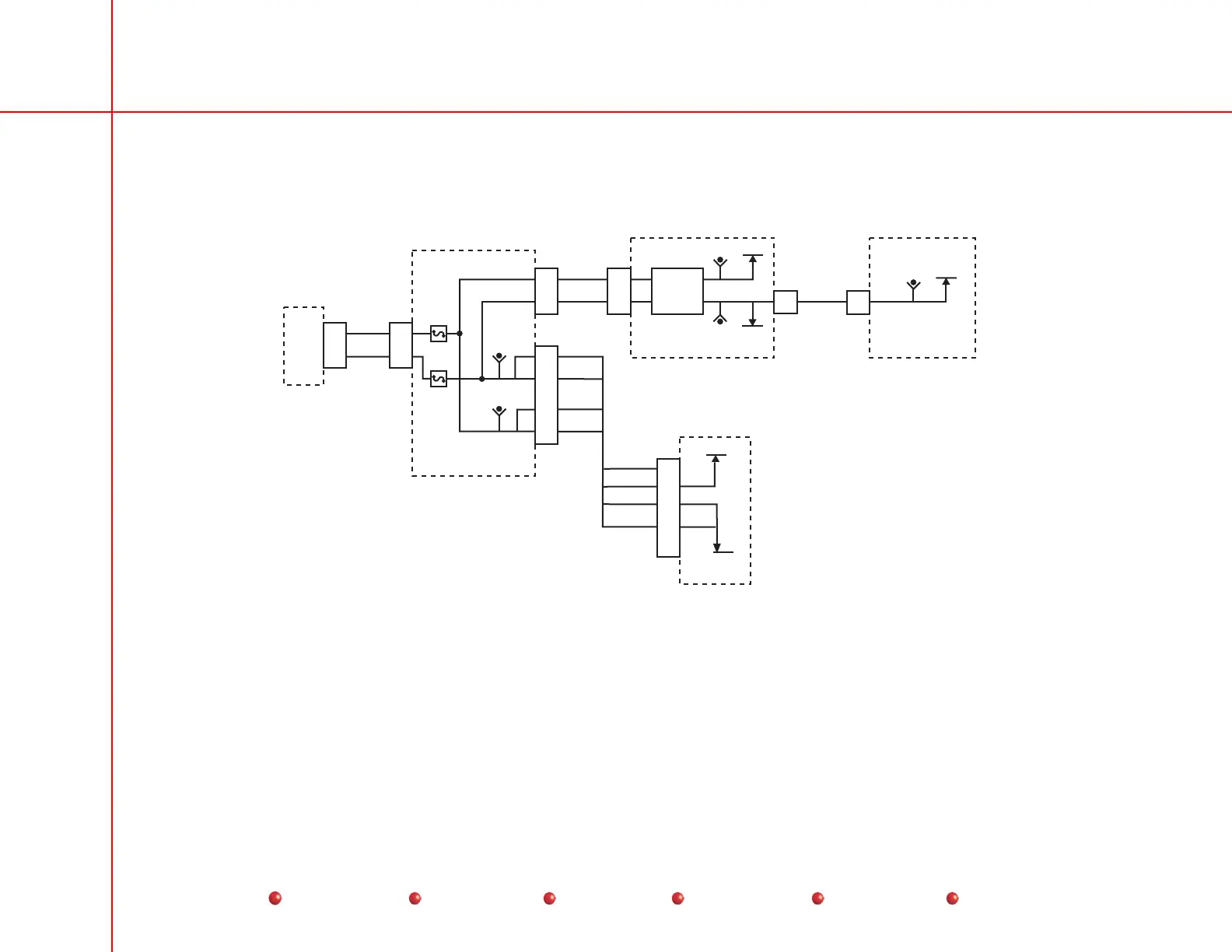
For an illustration of the PS1 ±15VDC output, refer to the following diagram:
12V
-12V
PS1
Generator Driver PCB
Filament Driver PCB
Power/Signal Interface PCB
TP5
TP4
+15 VDC
-15 VDC
F8
F7
P4
6
9
J2
13
11
P10
1
3
P2
1
4
P11
5
1
2
3
+15 VDC
+15 VDC POS_12V POS_12V
+15 VDC
-15 VDC
-15 VDC
-15 VDC
Backplane
P5
7
2
8
3
-15V
P11
4
P2
4
TP3
TP20
+12V
Power
Conditioning
TP9
+15V
PS1
±
15VDC Output
PS1 provides one line each of –15VDC and +15VDC to the Power/Signal Interface PCB, where each line is divided such that
there are 3 pairs exiting the board. One pair consists of a plus and a minus voltage. Another pair consists of two positive lines. A
third pair consists of two negative lines. Fuse F7 protects the three negative lines, and Fuse F8 takes care of the three positive
lines.
The ±15VDC pair exits the board from P10, and connects to the Generator Driver PCB, where they are processed by power
conditioning circuitry that produces -12 and +12 volts for operation of the board, and also the POS_12V, which exits via P11
going to the Filament Driver PCB to furnish that board’s 12-volt operating power.
7
Service
Periodic Maintenance
Contents
Schematics
Illustrated Parts
Installation
 Loading...


