OEC UroView
®
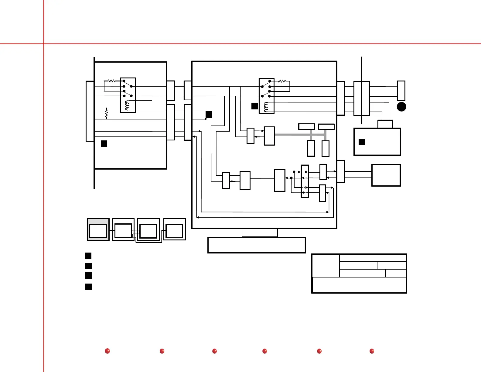
2800 Table/Generator Functional Block Diagrams
35
Service
Periodic Maintenance
Contents
Schematics
Illustrated Parts
Installation
J1
ARCNET_HI
WORKSTATION
REAR
PANEL
J6
P6
EMI
BOX
P3
SYSTEM INTERFACE PCB
EXTERNAL
INTERFACE PCB
P4
P2
P4
ARCNET_LO
U7
BD(7..0)
9
8
K1
U37
13
4
9
8
K1
13
4
U20
DATA(15..0)
U36
RS485
TRANSCEIVER
RS485
TRANSCEIVER
PENTIUM
ARCNET
CONTROLLER
DIAGNOSTIC
ARCNET
CONTROLLER
DIAGNOSTIC
PROCESSOR
MC68HC16Z1
REMOTE DIAGNOSTICS NODE
U43
1
2
7
6
1
4
20
18
7
6
1
4
20
18
1
2
INT_GOOD_HI
INT_GOOD_LO
3
8
POWER
CONTROL
PCB
P2
5
6
+12V
BD4
P1
ISOLAT_RLY_CNTL
P11
R1
150
R2
150
U32
U46
U16
P12
18
12
24
22
19
6
2
3
5
4
13
9
7
14
17
8
21
MODEM
DIAG_RXD
DIAG_TXD
MOD_TXD
MOD_RXD
DIAG_RXD
DIAG_TXD
11
Interconnect
Cable
U1
U2
DS1
DS2
DIAGNOSTIC LEDS
STATUS
LEDS
00-879184
00-879054
00-880315
1
2
7
6
26
20
19
1
2
26
19
20
7
8
1
2
1
2
8
8
7
7
3
2
1
1
See Workstation Power Distribution
Page 4 of 15
See Workstation Remote Diagnostics Interface Page 8 of 11
2
2
9
VCC
22 22
CONFIG 0
4
3
00
3
4
Shown in Workstation Standalone condition. Activated by CNCT_ON circuit.
See Workstation Power Distribution Page 4 of 15.
Diagnostic Processor U43 monitors the CONFIG 0 line and activates Relay K1 on the External Interface PCB
using the BD4 line when an external ARCNET cable is attached.
ARCNET_HI
ARCNET_LO
PASSIVE BACKPLANE
SLOT 2
2A
Workstation
System
Interface PCB
Table
Table/
Generator
Interface PCB
Collimator
Collimator
Interface PCB
X-ray Control
Console
X-ray Control
Interface PCB
Page 1 of 6
System Communications
System Interface PCB - ARCNET
07/01
2800
GE OEC Training
SYSCOMM.DS4
g
System Communications – System Interface PCB – ARCNET