OEC UroView
®
2800 Table/Generator Functional Block Diagrams
60
Service
Periodic Maintenance
Contents
Schematics
Illustrated Parts
Installation
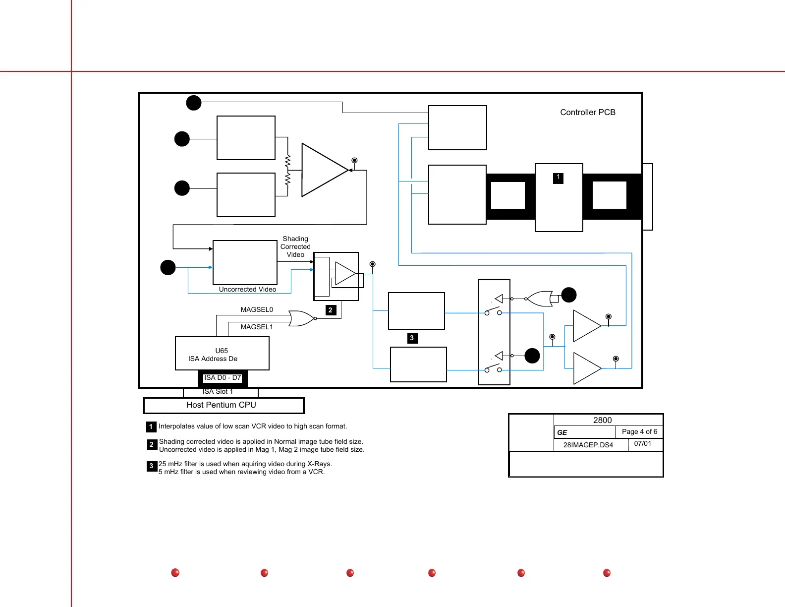
Image Path out of
Video Controller PCB
3A
3B
3C
3D
BP_CLAMP*
HSYNC*
VSYNC*
VID
Host Pentium CPU
ISA Slot 1
ISA D0 - D7
U65
ISA Address Decoder
Horizontal
Anti-Vignetting
Circuit
U23, U60, U54
Vertical
Anti-Vignetting
Circuit
U23, 60, U55
Summing
Amplifier
U57
TP47
AVIG
IN0
IN1
IN2
IN3
+
-
A0
U33
Voltage Controlled
Gain Amplifier
U32
U24
TP43
VCR
Anti Alias Filter
5 MHZ LP
Hi Res Video
Anti Alias Filter
25 MHZ LP
U34
DG411
TP50
3E
U24
3E
U41
MAX452
U56
MAX452
+
-
DC Restoration
Clamp Circuits
U34, U59, U43
A/D Converter
AD5800
U42
TP51
TP52
P3
To Image Processor
AD_IN0
to
AD_IN11
VC_D0
to
VC_D11
Pixel
Interpolator
U46
Video Controller PCB
1
1
Interpolates value of low scan VCR video to high scan format.
MAGSEL0
MAGSEL1
2
3
Shading
Corrected
Video
Uncorrected Video
2
Shading corrected video is applied in Normal image tube field size.
Uncorrected video is applied in Mag 1, Mag 2 image tube field size.
25 mHz filter is used when aquiring video during X-Rays.
5 mHz filter is used when reviewing video from a VCR.
3
Page 4 of 6
28IMAGEP.DS4
07/01
2800
GE OEC Training
g
Image Path Out of Video Controller PCB