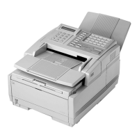
9
14. AC Power Socket: Connect the power cable supplied with
your fax machine into this socket.
15.
Cable Run: When installing the optional external handset,
feed the telephone line through this line run to TEL
terminals.
16.
TEL Terminals: Terminals for connecting an external
handset, external telephone, or answering machine to the fax
machine.
17.
LINE Terminal: Terminal for connecting the fax machine to
a telephone line.
18.
Expansion Slot Cover: Open this cover for access to
expansion slots for Network interface board and memory
expansion boards
19.
Image Drum Unit: The image drum unit contains the
photosensitive drum, which receives images from the LED
print head and transfers these images to the printing paper.
20.
Toner Cartridge: This black cylinder, installed inside the
image drum unit, contains black powder, which acts as the
ink for your fax machine.
21.
LED Print Head: This black bar is the part of your fax
machine, that transfers received or copied images onto the
image drum unit. Clean this bar each time you change a
toner cartridge.
14
15
16
17
18
1
A
B
C
2
D
E
F
3
G
H
I
4
J
K
L
5
M
N
6
P
R
S
7
T
U
V
8
W
X
Y
9
*
O
Q
Z
0
#
A
U
T
O
R
E
C
S
E
A
R
C
H
S
E
LE
CT
FUN
C
TIO
N
A
U
T
O
D
I
A
L
H
Y
P
H
E
N
R
E
D
I
A
L
C
O
P
Y
H
O
O
K
V.
R
E
Q
U
E
S
T
P
H
O
T
O
E
X
F
I
N
E
F
I
N
E
S
T
D
L
I
G
H
T
N
O
R
M
A
L
D
A
R
K
A
L
A
R
M
S
T
O
P
S
T
A
R
T
19
20
21