4. ADJUSTMENT
Oki Data CONFIDENTIAL
44983601TH Rev.1
4-15 /
4.1.3.3 Switch scan test
This self-diagnostic menu is used to check the entry sensor and the switch.
1. Entertheself-diagnosticmode(level1),pressthe[MENU
] or
[MENU
]
keyrepeatedly,andpressthe[OK]
keywhenthe"SWITCHSCAN"isdisplayedintheupperrowofthedisplayarea.(Pressingthe[MENU
]
key
incrementsthetestitemandpressingthe[MENU
]
key decrements the test item.)
SWITCH SCAN
2. Presseitherthe[MENU
]
or[MENU ] key until the desired menu item corresponding to the unit to be tested in
Table4-3isdisplayedinthelowerrowofthedisplayarea.(Pressingthe[MENU
]
key increments the test item
andpressingthe[MENU
]
key decrements the test item.)
3. Pressingthe[OK]keystartsthetest.Nameandpresentstatusofthecorrespondingunitaredisplayed.
PAPER ROTE:PU
1=H 2=L 3=H 4=L
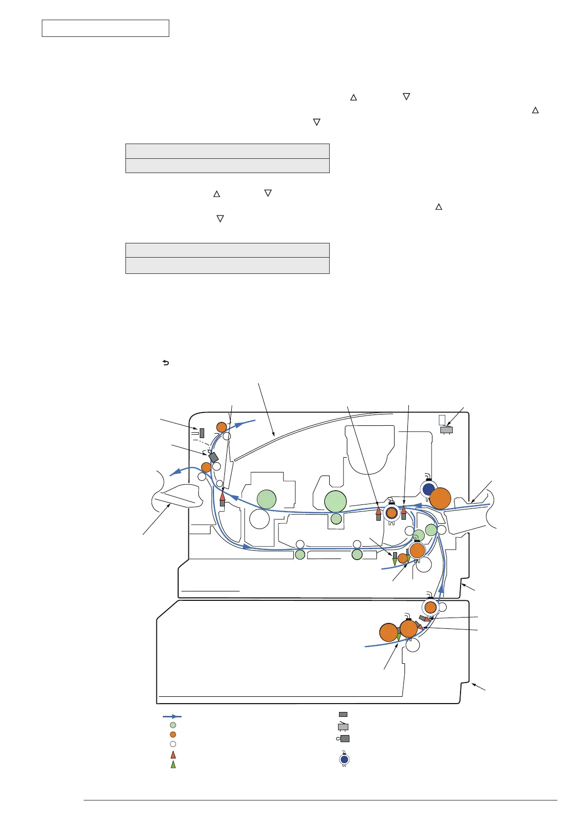
Activate therespective units. (Figure 4-1) Status of therespective units are displayed on the corresponding
areasoftheLCDdisplay.(Displaychangesdependingoneachsensor.RefertoTable4-3fordetails.)
4. Pressthe[CANCEL]keytoreturntothestatusofstep2.
5. Repeatsteps2to4asrequired.
6. Press the [
] key to exit the test. (Returns to the status of step 1.)
:Paper level indicator lever
:Driven roller
:Driving roller (Continuous rotation)
:Driving roller (Control rotation)
:Paper conveying route
:Indicating lever
:Photo sensor
:Micro switch
:Magnetic clutch
:Micro switch
Front
Back
Faceupstacker
EjectAssyopening
-closingsensor
2ndHoppingsensor
2ndEntrancesensor
Faceupstacker
opening-closingsensor
PaperendSensor
StackerCover
opening-closingsensor
Paperend/Cassette
presence-absencesensor
Cassettepresence
-absencesensor
Ejecting
sensorlever
Multipurposetray
Tray 1
Tray2(option)
Entrance
sensorlever
Writingoutsensorlever
Figure4-1Switchandsensorlocationdiagram