Do you have a question about the Oki ML 520/1 and is the answer not in the manual?
Assembly for the upper cover, available in Natural (N) and White (W) variants.
Assembly for the sheet guide, available in Natural (N) and White (W) variants.
Assembly for the access cover, available in Natural (N) and White (W) variants.
Main control board for the printer, available in FJIM and FJUK versions.
Board for the operator panel, identified as LEOP-2.
The main operation panel of the printer.
The complete assembly for the printer's print head.
Protective components including a circuit protector and fuse for 250V 1.0A.
Transformer units for 230/240V power supply.
Filter boards designed for 230V, 240V, and 110V power configurations.
The primary structural frame of the printer, in Natural and White finishes.
Tractor assemblies for paper feeding, in Natural and White variants.
Left and Right push tractor assemblies for paper handling.
The main frame assembly for the printer carriage.
Assembly for the back-up roller holder.
Cables for carriage operation, N and W variants.
Assemblies for the pull and bottom tractor mechanisms, Left and Right.
Cover assemblies for the tractor, in Natural and White variants.
Stand components for the bottom push mechanism, Left and Right.
Printed Circuit Board for RS 232C interface.
Printed Circuit Board for RS 422A interface.
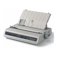
| Type | Dot Matrix Printer |
|---|---|
| Printing Method | Impact Dot Matrix |
| Number of Pins | 9 |
| Emulation | Epson FX, IBM ProPrinter |
| Noise Level | 55 dB |
| Interface | Parallel |
| Print Resolution | 240 x 216 dpi |
| Paper Handling | Continuous Forms, Cut Sheets |