3.3. Explosimetric detectors
Only explosimetric detectors of the "bridge" type can be connected to the SV 4B.
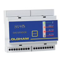
Surveyor 4B and the detector are connected together by a shielded cable with three active
conductors. The shielded cable is to be connected to the earth at one end only.
Terminals C1, C2 and C3 of Surveyor 4B and the detector are to be connected in opposite mode
(see Fig. 3).
The maximum loop resistance is 1.4 ohms.
For example: the maximum distance between Surveyor 4B and the detector will be 40 m with
conductors with a cross section of 1.5 mm².
3.4. External components
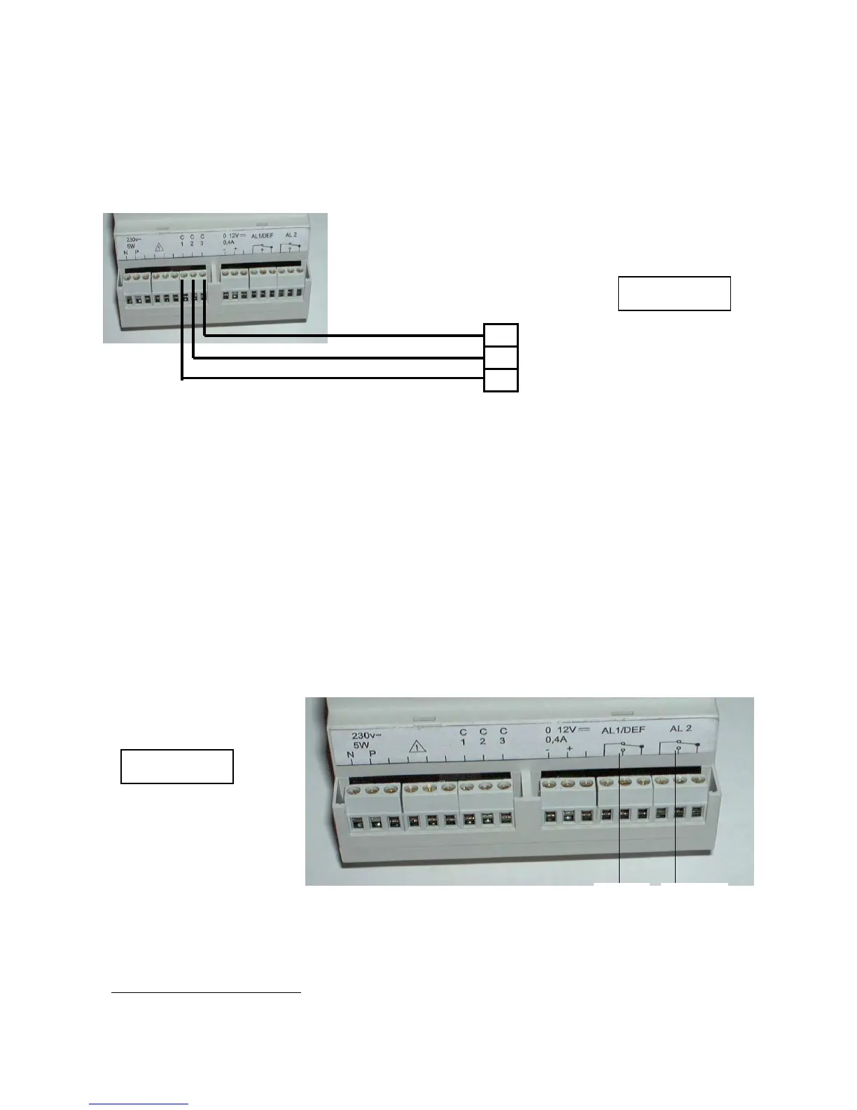
Surveyor 4B is equipped with the following two relays.
Relay 1 (REL 1), which is in mode, corresponds to the first gas alarm threshold and to the
"FAULT" alarm.
This relay is equipped with SPDT contacts available on the SV 4B terminal block (item 3, Fig.
5).
Relay 2 (REL 2), which is "negative safety" mode, corresponds to the second gas threshold
only. This relay is also equipped with SPDT contacts available on the SV 4B terminal block
(item 4, Fig. 5).
These both relays could be configured in positive and negative security (programmation by
welding slots on the printed circuit board: made only by OLDHAM or a skilled personal).
NB: The relay contacts are dry contacts, corresponding to the appliance without power supply.
Caution: The high-power solenoid valves cannot be directly remote controlled