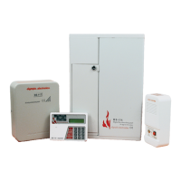
4. Connections
All connections to the panel must be made before connecting the battery and the
mains power supply.
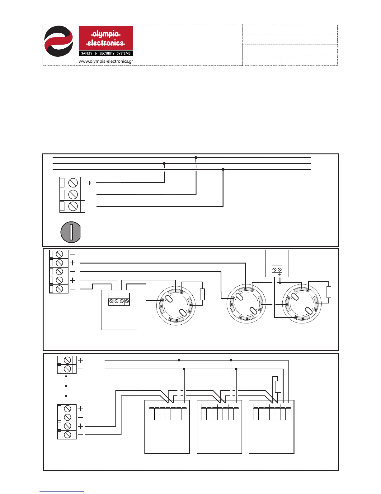
Each panel has terminal blocks for connecting 16 zones of detectors, break-glass call points
or other input devices. Each zone terminal block has a pre-fitted terminal resistor (5K6). This
resistor is removed and placed on the last device of the zone or it is left in it’s place if the
zone is not used.
The connections for all 16 zones are identical. What it show in figures 4 and 5 for zone 1 is
also valid for all the other zones.
1
2
3
5
4
Figure 4. Connecting 1 manual call point BS-536 and 1 detector base on zone 1and connecting 2 bases of
detectors on zone 2. One detector also has a BS-572 remote LED indicator connected to it.
Detector
base
Detector
base
5Κ6
I
N
IN
O
U
T
O
U
T
R
I
N
IN
O
U
T
O
U
T
R
Remote
LED
BS-572
R
Terminal
resistor
Detector
base
I
N
I
N
O
U
T
O
U
T
R
Manual call
point
BS-536
OUT IN
5Κ6
Terminal
resitor
FUSE
5x20 3A
L N
L
N
230V
~
Figure 3. Connection diagram with the mains voltage .
ΖΟΝΕ 1
ΖΟΝΕ 2
GND
6 from 21
921116000
Date
File
Code
Page
5Κ6
1
2
3
4
24 Vdc
monitor
ZONE
10-30V
NCNO CZONE
10-30V
NCNO CZONE
10-30V
NCNO C
Figure 5. Connecting 3 gas detectors BS-685 or BS-686. Besides connecting these detectors to the
zone we must also power them from the 24V dc monitor output.
Terminal
resistor
Gas
detector
BS-675
Gas
detector
BS-675
Gas
detector
BS-675
921116000_09_016
13/03/2013