Home
Olympia
Burner
LT-80
Page 9
Olympia LT-80 - Page 9
26 pages
Manual
Save Page as PDF
To Next Page
To Next Page
To Previous Page
To Previous Page
Loading...
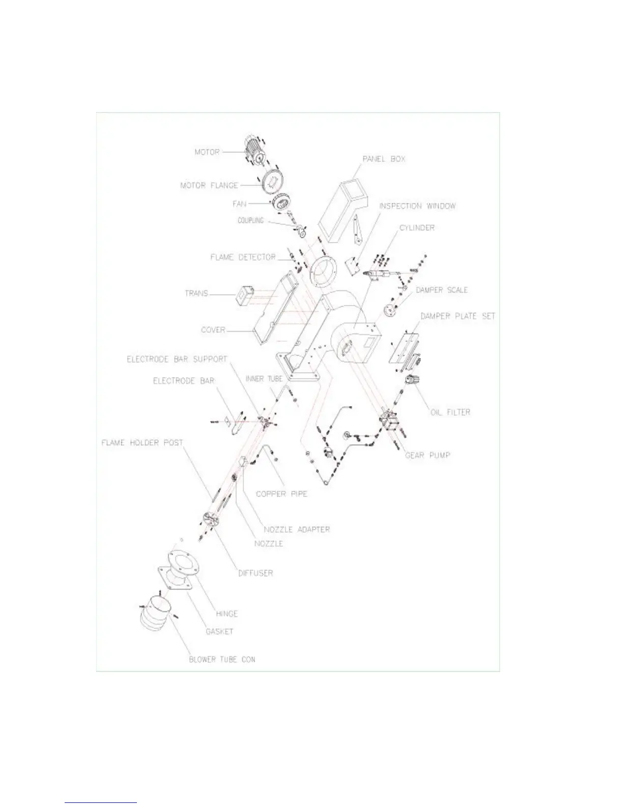
(3)
LT-
80U,100U,
150,200,2
50,300,400
,500,6
00,700
B
URNER
EXPLODED
D
RAWING.
*
LT-80T,
100T,1
50,200,250,
300
=
DAM
PER
MOTOR
LT-250,3
00,400,50
0,600,70
0
=
3NOZZLE
8
10
Table of Contents
Main Page
Contents
2
Product Introduction
3
Specifications
3
Combustion Performance Graph
4
Size and Dimension
5
Exploded Drawing of Burner and Parts Identification
7
How to Control Burner
10
Burner Combustion Furnace Dimension
10
To Install Burner
10
Diagram of Fuel Circulation System
11
Caution During Burner Installation
11
How to Lay Fuel Pipe
12
Cautions on Laying Fuel Pipe
12
Time Chart
13
Electric Circuit Diagram
14
Electric Diagram
15
How to Use Major Parts
16
Combustion Head Dimension
16
To Adjust Combustion Flow Rate
16
Damper Motor
17
Damper Adjustment
18
To Disassemble, Clean and Replace Nozzle
19
Flame Detector
21
Gear Pump
21
Ignition Transformer
22
General Burner Operation
23
Fuel Filter
23
To Maintain, Check and Service Burner
24
Trouble/Action Table
25
Troubleshooting
26